
User Manual
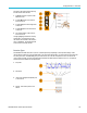
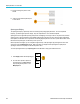
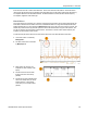
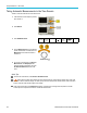
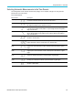
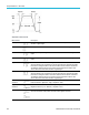
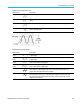
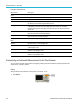
Table Of Contents
- toc
- Important safety information
- Compliance information
- Preface
- Installation
- Before Installation
- Operating Considerations
- Connecting Probes
- Securing the Oscilloscope
- Powering on the Oscilloscope
- Powering off the Oscilloscope
- Functional Check
- Compensating a TPP0250, TPP0500B or TPP1000 Passive Voltage Prob
- Compensating a non-TPP0250, non-TPP0500B or non-TPP1000 Passive
- Application Module Free Trial
- Installing an Application Module
- Upgrading Bandwidth
- Changing the Language of the User Interface or Keyboard
- Changing the Date and Time
- Signal Path Compensation
- Upgrading Firmware
- Connecting Your Oscilloscope to a Computer
- Connecting a USB Keyboard to Your Oscilloscope
- Get Acquainted with the Instrument
- Acquire the Signal
- Setting Up Analog Channels
- Using the Default Setup
- Using Autoset
- Acquisition Concepts
- Using FastAcq
- How the Analog Acquisition Modes Work
- Changing the Acquisition Mode, Record Length, and Delay Time
- Using Roll Mode
- Act on Event
- Setting Up a Serial or Parallel Bus
- Setting Up Digital Channels
- When and Why to Turn On MagniVu
- Using MagniVu
- Setting Up the RF Inputs
- Trigger Setup
- Display Waveform or Trace Data
- Adding and Removing a Waveform
- Setting the Display Style and Persistence
- Setting Waveform Intensity
- Scaling and Positioning a Waveform
- Setting Input Parameters
- Positioning and Labeling Bus Signals
- Positioning, Scaling, and Grouping Digital Channels
- Viewing Digital Channels
- Annotating the Screen
- Viewing the Trigger Frequency
- Displaying the Frequency Domain Menu
- Analyze Waveform or Trace Data
- Using Markers in the Frequency Domain
- Taking Automatic Measurements in the Time Domain
- Selecting Automatic Measurements in the Time Domain
- Customizing an Automatic Measurement in the Time Domain
- Taking Automatic Measurements in the Frequency Domain
- Taking Digital Voltmeter Measurements
- Taking Manual Measurements with Cursors
- Setting Up a Histogram
- Using Math Waveforms
- Using FFT
- Using Advanced Math
- Using Spectrum Math
- Using Reference Waveforms and Traces
- Using Wave Inspector to Manage Long Record Length Waveforms
- Auto-magnify
- Limit and Mask Testing
- Making Video Tests
- Making Automated Power Measurements
- Save and Recall Information
- Use the Arbitrary Function Generator
- Use the Application Modules
- Appendix A: Warranted Specifications
- Appendix B: TPP0250, TPP0500B and TPP1000: 250€MHz, 500€MHz and
- Appendix C: P6316 General-Purpose Logic Probe Information
- Appendix D: OpenSSL License
Analyze Wavefor
morTraceData
Amplitude measurements (cont.)
Measurement Description
Mean
The arithmetic mean over the entire w aveform or gated region.
Cycle Mean The arithmetic mean over the first cycle in the waveform or the first cycle in the gated
region.
RMS The true Root Mean Square voltage over the entire waveform or gated region.
Cycle RMS The true Root Mean Square voltage over the first cycle in the waveform or the first
cycle in the gated region.
Miscellaneous measurements
Measurement Description
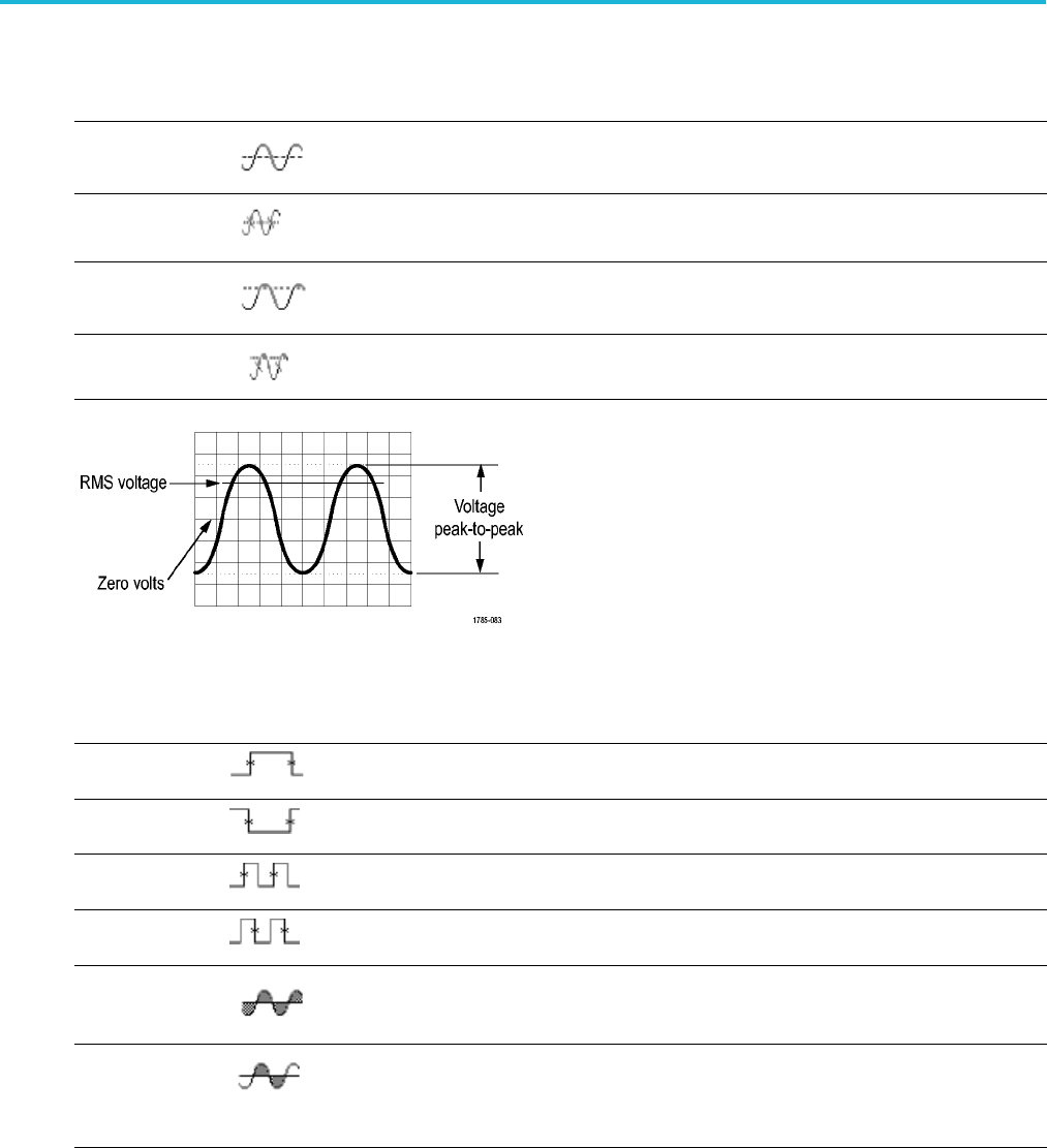
Positive Pulse
Count
The number of positive pulses that rise above the mid reference crossing in the waveform
or gate
d region.
Negative Pulse
Count
The nu
mber of negative pulses that fall below the mid reference crossing in the waveform
or gated region.
Risin
g Edge
Count
The number of positive transitions from the low reference value to the high reference
value in the waveform or gated region.
Falling Edge
Count
The number of negative transitions from the high reference value to the low reference
valu
e in the waveform or gated region.
Area Area measurement is a voltage over time measurement. It returns the area over the
ent
ire waveform or gated region in volt-seconds. Area measured above ground is
positive; area measured below ground is negative.
Cycle Area A voltage over time measurement. The measurement is the area over the first c ycle
in the waveform or the first cycle in the gated region expressed in volt-seconds. The
ar
ea above the common reference point is positive, and the area below the c ommon
reference point is negative.
MDO3000 Series Oscilloscopes User Manual 127