
User Manual
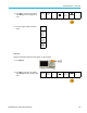
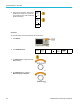
Table Of Contents
- toc
- Important safety information
- Compliance information
- Preface
- Installation
- Before Installation
- Operating Considerations
- Connecting Probes
- Securing the Oscilloscope
- Powering on the Oscilloscope
- Powering off the Oscilloscope
- Functional Check
- Compensating a TPP0250, TPP0500B or TPP1000 Passive Voltage Prob
- Compensating a non-TPP0250, non-TPP0500B or non-TPP1000 Passive
- Application Module Free Trial
- Installing an Application Module
- Upgrading Bandwidth
- Changing the Language of the User Interface or Keyboard
- Changing the Date and Time
- Signal Path Compensation
- Upgrading Firmware
- Connecting Your Oscilloscope to a Computer
- Connecting a USB Keyboard to Your Oscilloscope
- Get Acquainted with the Instrument
- Acquire the Signal
- Setting Up Analog Channels
- Using the Default Setup
- Using Autoset
- Acquisition Concepts
- Using FastAcq
- How the Analog Acquisition Modes Work
- Changing the Acquisition Mode, Record Length, and Delay Time
- Using Roll Mode
- Act on Event
- Setting Up a Serial or Parallel Bus
- Setting Up Digital Channels
- When and Why to Turn On MagniVu
- Using MagniVu
- Setting Up the RF Inputs
- Trigger Setup
- Display Waveform or Trace Data
- Adding and Removing a Waveform
- Setting the Display Style and Persistence
- Setting Waveform Intensity
- Scaling and Positioning a Waveform
- Setting Input Parameters
- Positioning and Labeling Bus Signals
- Positioning, Scaling, and Grouping Digital Channels
- Viewing Digital Channels
- Annotating the Screen
- Viewing the Trigger Frequency
- Displaying the Frequency Domain Menu
- Analyze Waveform or Trace Data
- Using Markers in the Frequency Domain
- Taking Automatic Measurements in the Time Domain
- Selecting Automatic Measurements in the Time Domain
- Customizing an Automatic Measurement in the Time Domain
- Taking Automatic Measurements in the Frequency Domain
- Taking Digital Voltmeter Measurements
- Taking Manual Measurements with Cursors
- Setting Up a Histogram
- Using Math Waveforms
- Using FFT
- Using Advanced Math
- Using Spectrum Math
- Using Reference Waveforms and Traces
- Using Wave Inspector to Manage Long Record Length Waveforms
- Auto-magnify
- Limit and Mask Testing
- Making Video Tests
- Making Automated Power Measurements
- Save and Recall Information
- Use the Arbitrary Function Generator
- Use the Application Modules
- Appendix A: Warranted Specifications
- Appendix B: TPP0250, TPP0500B and TPP1000: 250€MHz, 500€MHz and
- Appendix C: P6316 General-Purpose Logic Probe Information
- Appendix D: OpenSSL License
Analyze Wavefor
morTraceData
5. Push OK Snapshot All Measurem ents .
OK
Snapshot
All Mea-
surements
6. View results.
Snapshot on 1
Period
+Width
Burst W
Rise
+Duty
+Over
High
Max
Ampl
Mean
RMS
Area
+Edges
+Pulses
: 312.2s
: 103.7s
: 936.5s
: 1.452s
: 33.23%
: 7.143%
: 9.200 V
: 10.40 V
: 16.80 V
: -5.396 V
: 7.769 V
:-21.58mVs
:1
:2
Freq
–Width
Fall
±Over
–Duty
–Over
Low
Min
Pk-Pk
CycleMean
CycleRMS
CycleArea
-Edges
-Pulses
: 3.203 kHz
: 208.5s
1.144s
: 14.286%
: 66.77 %
: 7.143 %
: -7.600 V
: -8.800 V
: 19.20 V
: -5.396 V
: 8.206 V
: -654.6Vs
:0
:2
Reference Levels
Reference levels determine how time-related
measur
ements are taken. For example, they are
used in calculating rise and fall times.
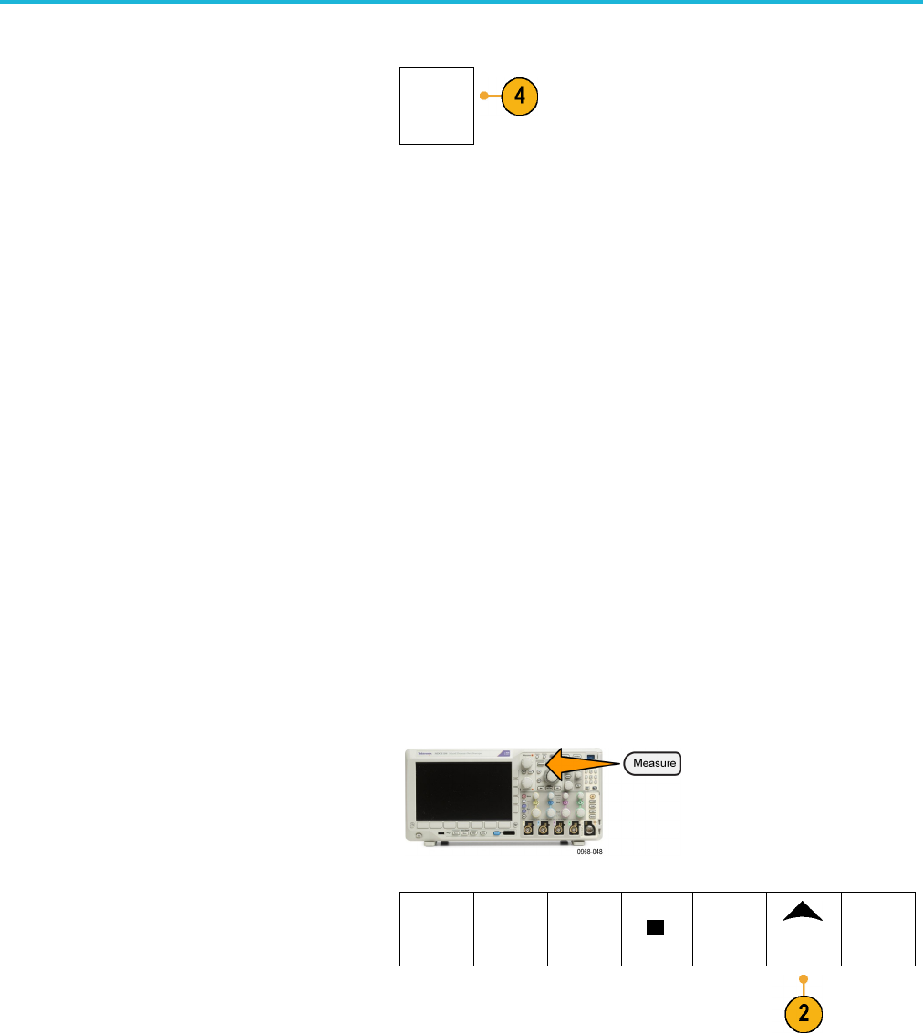
1. Push Measure.
2. Push M
ore as many times as needed to
select Reference Levels from the resulting
pop-up menu.
Add Me
a-
surement
Remov
e
Measure-
ment
Indic
ators
DVM
DC
Wave-
form His-
tograms
More
MDO3000 Series Oscilloscopes User Manual 131