
User Manual
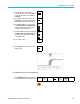
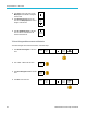
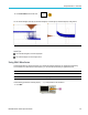
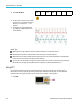
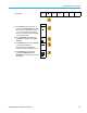
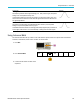
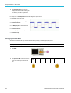
Table Of Contents
- toc
- Important safety information
- Compliance information
- Preface
- Installation
- Before Installation
- Operating Considerations
- Connecting Probes
- Securing the Oscilloscope
- Powering on the Oscilloscope
- Powering off the Oscilloscope
- Functional Check
- Compensating a TPP0250, TPP0500B or TPP1000 Passive Voltage Prob
- Compensating a non-TPP0250, non-TPP0500B or non-TPP1000 Passive
- Application Module Free Trial
- Installing an Application Module
- Upgrading Bandwidth
- Changing the Language of the User Interface or Keyboard
- Changing the Date and Time
- Signal Path Compensation
- Upgrading Firmware
- Connecting Your Oscilloscope to a Computer
- Connecting a USB Keyboard to Your Oscilloscope
- Get Acquainted with the Instrument
- Acquire the Signal
- Setting Up Analog Channels
- Using the Default Setup
- Using Autoset
- Acquisition Concepts
- Using FastAcq
- How the Analog Acquisition Modes Work
- Changing the Acquisition Mode, Record Length, and Delay Time
- Using Roll Mode
- Act on Event
- Setting Up a Serial or Parallel Bus
- Setting Up Digital Channels
- When and Why to Turn On MagniVu
- Using MagniVu
- Setting Up the RF Inputs
- Trigger Setup
- Display Waveform or Trace Data
- Adding and Removing a Waveform
- Setting the Display Style and Persistence
- Setting Waveform Intensity
- Scaling and Positioning a Waveform
- Setting Input Parameters
- Positioning and Labeling Bus Signals
- Positioning, Scaling, and Grouping Digital Channels
- Viewing Digital Channels
- Annotating the Screen
- Viewing the Trigger Frequency
- Displaying the Frequency Domain Menu
- Analyze Waveform or Trace Data
- Using Markers in the Frequency Domain
- Taking Automatic Measurements in the Time Domain
- Selecting Automatic Measurements in the Time Domain
- Customizing an Automatic Measurement in the Time Domain
- Taking Automatic Measurements in the Frequency Domain
- Taking Digital Voltmeter Measurements
- Taking Manual Measurements with Cursors
- Setting Up a Histogram
- Using Math Waveforms
- Using FFT
- Using Advanced Math
- Using Spectrum Math
- Using Reference Waveforms and Traces
- Using Wave Inspector to Manage Long Record Length Waveforms
- Auto-magnify
- Limit and Mask Testing
- Making Video Tests
- Making Automated Power Measurements
- Save and Recall Information
- Use the Arbitrary Function Generator
- Use the Application Modules
- Appendix A: Warranted Specifications
- Appendix B: TPP0250, TPP0500B and TPP1000: 250€MHz, 500€MHz and
- Appendix C: P6316 General-Purpose Logic Probe Information
- Appendix D: OpenSSL License
Analyze Wavefor
morTraceData
2. Push Dual Wfm Math.
Dual Wfm
Math
FFT Advanced
Math
Spectrum
Math
(M) Label
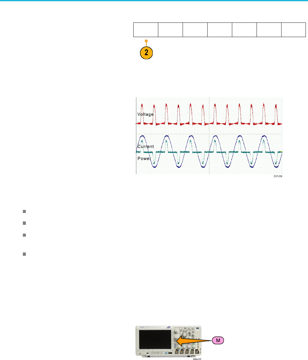
3. Onthesideme
nu, set the sources to either
channel 1, 2, 3, 4, or reference w aveforms
R1, 2, 3,or4. Choose the +, –, x,or÷
operators.
4. For example, you might calculate power
by multiplying a voltage waveform and a
current wa
veform.
Quick Tips
Math wa
veforms can be created from channel or reference waveforms or a combination of them.
Measur
ements can be taken on m ath w aveforms in the same way as on channel waveforms.
Math w
aveforms derive their horizontal scale and position from the sources in their math expressions. Adjusting these
controls for the source waveforms also adjusts the math waveform.
You can zoom in on math waveforms using the inner knob of th e Pan-Zoom control. Use the outer knob for positioning
the zoomed area. (See page 149, Using Wave Inspector to Manage Long Record Length Waveforms.)
Usin
g FFT
An FFT function breaks down signals into component frequencies, which the oscilloscope uses to display a graph of
the frequency domain of a signal, as opposed to the oscilloscope's standard time domain graph. You can match these
frequencies with known system frequencies, such as system clocks, oscillators, or power supplies.
1. Push Math.
142 MDO3000 Series Oscilloscopes User Manual