
User Manual
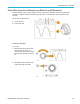
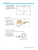
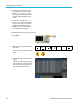
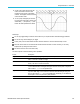


Table Of Contents
- toc
- Important safety information
- Compliance information
- Preface
- Installation
- Before Installation
- Operating Considerations
- Connecting Probes
- Securing the Oscilloscope
- Powering on the Oscilloscope
- Powering off the Oscilloscope
- Functional Check
- Compensating a TPP0250, TPP0500B or TPP1000 Passive Voltage Prob
- Compensating a non-TPP0250, non-TPP0500B or non-TPP1000 Passive
- Application Module Free Trial
- Installing an Application Module
- Upgrading Bandwidth
- Changing the Language of the User Interface or Keyboard
- Changing the Date and Time
- Signal Path Compensation
- Upgrading Firmware
- Connecting Your Oscilloscope to a Computer
- Connecting a USB Keyboard to Your Oscilloscope
- Get Acquainted with the Instrument
- Acquire the Signal
- Setting Up Analog Channels
- Using the Default Setup
- Using Autoset
- Acquisition Concepts
- Using FastAcq
- How the Analog Acquisition Modes Work
- Changing the Acquisition Mode, Record Length, and Delay Time
- Using Roll Mode
- Act on Event
- Setting Up a Serial or Parallel Bus
- Setting Up Digital Channels
- When and Why to Turn On MagniVu
- Using MagniVu
- Setting Up the RF Inputs
- Trigger Setup
- Display Waveform or Trace Data
- Adding and Removing a Waveform
- Setting the Display Style and Persistence
- Setting Waveform Intensity
- Scaling and Positioning a Waveform
- Setting Input Parameters
- Positioning and Labeling Bus Signals
- Positioning, Scaling, and Grouping Digital Channels
- Viewing Digital Channels
- Annotating the Screen
- Viewing the Trigger Frequency
- Displaying the Frequency Domain Menu
- Analyze Waveform or Trace Data
- Using Markers in the Frequency Domain
- Taking Automatic Measurements in the Time Domain
- Selecting Automatic Measurements in the Time Domain
- Customizing an Automatic Measurement in the Time Domain
- Taking Automatic Measurements in the Frequency Domain
- Taking Digital Voltmeter Measurements
- Taking Manual Measurements with Cursors
- Setting Up a Histogram
- Using Math Waveforms
- Using FFT
- Using Advanced Math
- Using Spectrum Math
- Using Reference Waveforms and Traces
- Using Wave Inspector to Manage Long Record Length Waveforms
- Auto-magnify
- Limit and Mask Testing
- Making Video Tests
- Making Automated Power Measurements
- Save and Recall Information
- Use the Arbitrary Function Generator
- Use the Application Modules
- Appendix A: Warranted Specifications
- Appendix B: TPP0250, TPP0500B and TPP1000: 250€MHz, 500€MHz and
- Appendix C: P6316 General-Purpose Logic Probe Information
- Appendix D: OpenSSL License

Analyze Wavefor
morTraceData
Search Description
Rise/Fall Tim
e
Search for ris
ing and/or falling edges that are >, <, =, or a user specified time.
Bus
Parallel: Sea
rch for a binary or hex value.
I
2
C: Search for Start, Repeated Start, Stop, Missing Ack, Address, Data, or Address and
Data.
SPI: Search f
or SS Active, MOSI, MISO, or MOSI & MISO
RS-232, RS-422, RS-485, UART: Search for Tx Start Bit, Rx Start Bit, Tx End of Packet, Rx
End of Packet, Tx Data, Rx Data, Tx Parity Error, Rx Parity Error.
CAN, CAN FD:
Search for Start of Frame, Type of Frame (Data, Remote, Error, Overload),
Identifier (standard or extended), D ata, Identifier and Data, End of Frame, Bit Suffing Error,
Missing Ack, FD BRS Bit, FD ESI Bit, Form Error, or Any Error
1
LIN: Searc
h for Synch, Identifier, Data, ID & Data, Wakeup Frame, Sleep Frame, Error
FlexRay: Search for Start of Frame, Type of Frame, Identifier, Cycle Count, H eader Fields,
Data, ID & Data, End of Frame, Error
Audio: Sea
rch for Word Select or Data
USB: Search for Sync, Reset, Suspend, Resume, End of Packet, Token (Address) Packet,
Data Packet, Handshake Packet, Special Packet, or Error
MIL-STD-
1553: Search for Sync, Command, Status, Data, Time (RT/IMG), Error
ARINC429: Search for Word Start, Label, Data, Label and Data, Word End, or Error
1
FD BRS Bit, FD ESI Bit, Form Error and Any E rror are available only when CA N FD is selected as BUS.
Auto-magnify
As you a
djust the horizontal scale control to faster time/division settings, the MDO3000 Series automatically increases the
sample rate to keep acquiring the same record length in the shorter period of time. Eventually though, the MDO3000 S eries
hits its maximum sample rate. Once the instrument is at its fastest sample rate, further changes to faster timebase s ettings
cause t
he oscilloscope to operate in Auto-magnify mode, where the oscilloscope shows the faster desired time/division
setting and continues to acquire the desired record length. The result is that the oscilloscope cannot show all of the acquired
points within the desired time/division setting.
Instead, the oscilloscope shows you only a portion of the entire record in the time-domain graticule. This feature provides you
with a
way to magnify a portion of the record without having to use the smaller zoom screen display. This feature gives you
the maximum benefit of the sample rate / record length c ombination in your oscilloscope. With Auto-magnify, you have
access to the full record length at the maximum sample rate.
NOTE
. Auto-magnify only comes on when the zoom feature is turned off.
154 MDO3000 Series Oscilloscopes User Manual