
User Manual
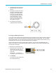
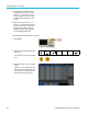
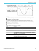
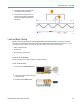


Table Of Contents
- toc
- Important safety information
- Compliance information
- Preface
- Installation
- Before Installation
- Operating Considerations
- Connecting Probes
- Securing the Oscilloscope
- Powering on the Oscilloscope
- Powering off the Oscilloscope
- Functional Check
- Compensating a TPP0250, TPP0500B or TPP1000 Passive Voltage Prob
- Compensating a non-TPP0250, non-TPP0500B or non-TPP1000 Passive
- Application Module Free Trial
- Installing an Application Module
- Upgrading Bandwidth
- Changing the Language of the User Interface or Keyboard
- Changing the Date and Time
- Signal Path Compensation
- Upgrading Firmware
- Connecting Your Oscilloscope to a Computer
- Connecting a USB Keyboard to Your Oscilloscope
- Get Acquainted with the Instrument
- Acquire the Signal
- Setting Up Analog Channels
- Using the Default Setup
- Using Autoset
- Acquisition Concepts
- Using FastAcq
- How the Analog Acquisition Modes Work
- Changing the Acquisition Mode, Record Length, and Delay Time
- Using Roll Mode
- Act on Event
- Setting Up a Serial or Parallel Bus
- Setting Up Digital Channels
- When and Why to Turn On MagniVu
- Using MagniVu
- Setting Up the RF Inputs
- Trigger Setup
- Display Waveform or Trace Data
- Adding and Removing a Waveform
- Setting the Display Style and Persistence
- Setting Waveform Intensity
- Scaling and Positioning a Waveform
- Setting Input Parameters
- Positioning and Labeling Bus Signals
- Positioning, Scaling, and Grouping Digital Channels
- Viewing Digital Channels
- Annotating the Screen
- Viewing the Trigger Frequency
- Displaying the Frequency Domain Menu
- Analyze Waveform or Trace Data
- Using Markers in the Frequency Domain
- Taking Automatic Measurements in the Time Domain
- Selecting Automatic Measurements in the Time Domain
- Customizing an Automatic Measurement in the Time Domain
- Taking Automatic Measurements in the Frequency Domain
- Taking Digital Voltmeter Measurements
- Taking Manual Measurements with Cursors
- Setting Up a Histogram
- Using Math Waveforms
- Using FFT
- Using Advanced Math
- Using Spectrum Math
- Using Reference Waveforms and Traces
- Using Wave Inspector to Manage Long Record Length Waveforms
- Auto-magnify
- Limit and Mask Testing
- Making Video Tests
- Making Automated Power Measurements
- Save and Recall Information
- Use the Arbitrary Function Generator
- Use the Application Modules
- Appendix A: Warranted Specifications
- Appendix B: TPP0250, TPP0500B and TPP1000: 250€MHz, 500€MHz and
- Appendix C: P6316 General-Purpose Logic Probe Information
- Appendix D: OpenSSL License

Analyze Wavefor
morTraceData
:REM "I nitialize the custom mask"
:MASK:CUSTom I
NIT
:REM "M ask Setup I nformation"
:MASK:USER:LABEL " Custom Mask of STS-1"
:MASK:USER:A
MPLITUDE 1.0000
:MASK:USER:VSCALE 200.0000E-3
:MASK:USER:VPOS -2.5000
:MASK:USER:
VOFFSET 0.0E+0
:MASK:USER:HSCALE 4.0000E-9
:MASK:USER:HTRIGPOS 318.1000E-3
:MASK:USER:
WIDTH 2 9.5500E-9
:MASK:USER:RECORDLENGTH 1000
:MASK:USER:TRIGTOSAMP 7.2750E-9
:REM "Mask P
oints are Defined in Volts and Seconds"
:REM "P oints in a segment must be defined in counter clockwise order"
:REM "A single point at 0,0 indica tes an empt y segment"
:MASK:USE
R:SEG1:POINTS -7.500 0E-9,1.5000,-7.5000E-9,100.0000E-3,-5.1656E-
9,100.0000E-3,-1.3536E-9,500.0000E-3,-1.3 536E-9,1.2000,7.2750E-9,1.1000,15.9036E-
9,1.2000,15.9036E-9,500.0000E-3,19.7156E- 9,100.0000E-3,22.0500E-9,100.0000E-
3,22.0500
E-9,1.5000
:MASK:USER:SEG2:POINTS -7.500 0E-9,-500.0000E-3,22.0500E-9,-500.0000E-3,22.0500E-9,-
100.0000E-3,13.4214E-9,-200.0000E-3,13.42 14E-9,500.0000E-3,11.6780E-9,800.0000E-
3,7.2750
E-9,900.0000E-3,2.8720E-9,800.0000E-3,1.1 286E-9,500.0000E-3,1.1286E-9,-
200.0000E-3,-7.5000E-9,-100.0000E-3
:MASK:USER:SEG3:POINTS 0.0E+0 ,0.0E+0
:MASK:U
SER:SEG4:POINTS 0.0E +0,0.0E+0
:MASK:USER:SEG5:POINTS 0.0E+0 ,0.0E+0
:MASK:USER:SEG6:POINTS 0.0E+0 ,0.0E+0
:MASK:U
SER:SEG7:POINTS 0.0E +0,0.0E+0
:MASK:USER:SEG8:POINTS 0.0E+0 ,0.0E+0
Createacustommaskviaaremoteinterface. To use remote interface commands to create and edit a mask, see
the MDO3000 Series Oscilloscope Programmer Manual.
Set Up the Test
To set up the limit or mask test, connect the test source to the oscilloscope. For a limit test, set the test source horizontal and
vertical settings to the same values that were used to create the limit test m ask. Push Set Up Test on the lower menu and set
the following:
Setting Description
Source Channel Select the channel to be tested
Violation Threshold
Set the number of violations that can occur before a test s tatus is considered failed.
Stop After Waveform Set the test to stop after a set number of waveforms.
Stop After Time Set the test to stop after a set amount of time elapses.
MDO3000 Series Oscilloscopes User Manual 157