
User Manual
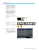
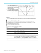


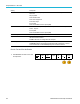
Table Of Contents
- toc
- Important safety information
- Compliance information
- Preface
- Installation
- Before Installation
- Operating Considerations
- Connecting Probes
- Securing the Oscilloscope
- Powering on the Oscilloscope
- Powering off the Oscilloscope
- Functional Check
- Compensating a TPP0250, TPP0500B or TPP1000 Passive Voltage Prob
- Compensating a non-TPP0250, non-TPP0500B or non-TPP1000 Passive
- Application Module Free Trial
- Installing an Application Module
- Upgrading Bandwidth
- Changing the Language of the User Interface or Keyboard
- Changing the Date and Time
- Signal Path Compensation
- Upgrading Firmware
- Connecting Your Oscilloscope to a Computer
- Connecting a USB Keyboard to Your Oscilloscope
- Get Acquainted with the Instrument
- Acquire the Signal
- Setting Up Analog Channels
- Using the Default Setup
- Using Autoset
- Acquisition Concepts
- Using FastAcq
- How the Analog Acquisition Modes Work
- Changing the Acquisition Mode, Record Length, and Delay Time
- Using Roll Mode
- Act on Event
- Setting Up a Serial or Parallel Bus
- Setting Up Digital Channels
- When and Why to Turn On MagniVu
- Using MagniVu
- Setting Up the RF Inputs
- Trigger Setup
- Display Waveform or Trace Data
- Adding and Removing a Waveform
- Setting the Display Style and Persistence
- Setting Waveform Intensity
- Scaling and Positioning a Waveform
- Setting Input Parameters
- Positioning and Labeling Bus Signals
- Positioning, Scaling, and Grouping Digital Channels
- Viewing Digital Channels
- Annotating the Screen
- Viewing the Trigger Frequency
- Displaying the Frequency Domain Menu
- Analyze Waveform or Trace Data
- Using Markers in the Frequency Domain
- Taking Automatic Measurements in the Time Domain
- Selecting Automatic Measurements in the Time Domain
- Customizing an Automatic Measurement in the Time Domain
- Taking Automatic Measurements in the Frequency Domain
- Taking Digital Voltmeter Measurements
- Taking Manual Measurements with Cursors
- Setting Up a Histogram
- Using Math Waveforms
- Using FFT
- Using Advanced Math
- Using Spectrum Math
- Using Reference Waveforms and Traces
- Using Wave Inspector to Manage Long Record Length Waveforms
- Auto-magnify
- Limit and Mask Testing
- Making Video Tests
- Making Automated Power Measurements
- Save and Recall Information
- Use the Arbitrary Function Generator
- Use the Application Modules
- Appendix A: Warranted Specifications
- Appendix B: TPP0250, TPP0500B and TPP1000: 250€MHz, 500€MHz and
- Appendix C: P6316 General-Purpose Logic Probe Information
- Appendix D: OpenSSL License
Analyze Wavefor
morTraceData
Setting Description
Select Action
on Failure
Set how the osc
illoscope responds to test failure. You can set multiple actions.
These are:
Stop acquisition
Save waveform
to file
Save screen image to file
Print screen image
Aux out pulse
Set a remote interface service request (SRQ)
Select Action on Test Completion Set how the oscilloscope will respond to test completion. You can set multiple
actions. They are:
Aux out pul
se
Set a remote interface service request (SRQ)
Pre-Test D
elay
Set a delay before starting a test.
Repeat Te
st
Set On for the test to repeat when it has run the minimum number of waveforms or
the minimum amount of time.
Set Off t
or the test to run a single time and not repeat.
Mask Polarity
Set the m
ask polarity to use during the test. When Both is selected, the test will run
with Normal polarity for about half of the expected number of waveforms or amount
of time and then will run with Inverted polarity for the remained of the test.
Run the Test and View the Results
1. Push Run Test on the lower menu to start
and stop the test.
Application
Limit/Mask
Test
Set Up
Mask
On
Selec
t
Mask
Limit Test
Creat
e
Limit Mask
Set Up
Test
1
Run Test
On |
Off
Show
Results
Off
158 MDO3000 Series Oscilloscopes User Manual