
User Manual
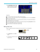
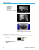
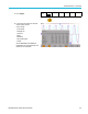
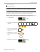
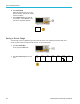
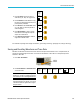
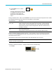
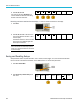
Table Of Contents
- toc
- Important safety information
- Compliance information
- Preface
- Installation
- Before Installation
- Operating Considerations
- Connecting Probes
- Securing the Oscilloscope
- Powering on the Oscilloscope
- Powering off the Oscilloscope
- Functional Check
- Compensating a TPP0250, TPP0500B or TPP1000 Passive Voltage Prob
- Compensating a non-TPP0250, non-TPP0500B or non-TPP1000 Passive
- Application Module Free Trial
- Installing an Application Module
- Upgrading Bandwidth
- Changing the Language of the User Interface or Keyboard
- Changing the Date and Time
- Signal Path Compensation
- Upgrading Firmware
- Connecting Your Oscilloscope to a Computer
- Connecting a USB Keyboard to Your Oscilloscope
- Get Acquainted with the Instrument
- Acquire the Signal
- Setting Up Analog Channels
- Using the Default Setup
- Using Autoset
- Acquisition Concepts
- Using FastAcq
- How the Analog Acquisition Modes Work
- Changing the Acquisition Mode, Record Length, and Delay Time
- Using Roll Mode
- Act on Event
- Setting Up a Serial or Parallel Bus
- Setting Up Digital Channels
- When and Why to Turn On MagniVu
- Using MagniVu
- Setting Up the RF Inputs
- Trigger Setup
- Display Waveform or Trace Data
- Adding and Removing a Waveform
- Setting the Display Style and Persistence
- Setting Waveform Intensity
- Scaling and Positioning a Waveform
- Setting Input Parameters
- Positioning and Labeling Bus Signals
- Positioning, Scaling, and Grouping Digital Channels
- Viewing Digital Channels
- Annotating the Screen
- Viewing the Trigger Frequency
- Displaying the Frequency Domain Menu
- Analyze Waveform or Trace Data
- Using Markers in the Frequency Domain
- Taking Automatic Measurements in the Time Domain
- Selecting Automatic Measurements in the Time Domain
- Customizing an Automatic Measurement in the Time Domain
- Taking Automatic Measurements in the Frequency Domain
- Taking Digital Voltmeter Measurements
- Taking Manual Measurements with Cursors
- Setting Up a Histogram
- Using Math Waveforms
- Using FFT
- Using Advanced Math
- Using Spectrum Math
- Using Reference Waveforms and Traces
- Using Wave Inspector to Manage Long Record Length Waveforms
- Auto-magnify
- Limit and Mask Testing
- Making Video Tests
- Making Automated Power Measurements
- Save and Recall Information
- Use the Arbitrary Function Generator
- Use the Application Modules
- Appendix A: Warranted Specifications
- Appendix B: TPP0250, TPP0500B and TPP1000: 250€MHz, 500€MHz and
- Appendix C: P6316 General-Purpose Logic Probe Information
- Appendix D: OpenSSL License
Save and Recall I
nformation
MIN for a minimum hold trace
TIQ for a baseband I & Q file
NOTE. Analog,
digital, and RF waveforms and traces and those waveforms and traces derived from them (such as math
and references) can be saved to an ISF file. When saving all c hannels in ISF format, a group of files will be saved. Each
will have the same value for XXXX, but the YYY values will be set to the different channels that were turned on when the
Save All Wave
forms operation was performed.
The XXXX val
ue will automatically incr ement each time you save a file of the same type. For example, the first time you save
a file, that file is named tek00000. The next time you save the same type of file, the file will be named tek00001.
Editing fil
e, directory, reference waveform, or instrument setup names.
Give files descriptive names that you c an
recognize at a later date. To edit file names, directory names, reference waveform and instrument setup labels:
1. Push Save /
Recall Menu.
2. Push Save Screen Image, Save Waveform,
or Save S
etup.
Save
Screen
Image
Save
Waveform
Save
Setup
Recall
Waveform
Recall
Setup
Assign
Save|to
Setup
File
Utilities
3. For wa
veform or setup files, enter the file
manager by pushing the appropriate side
menu button.
To File
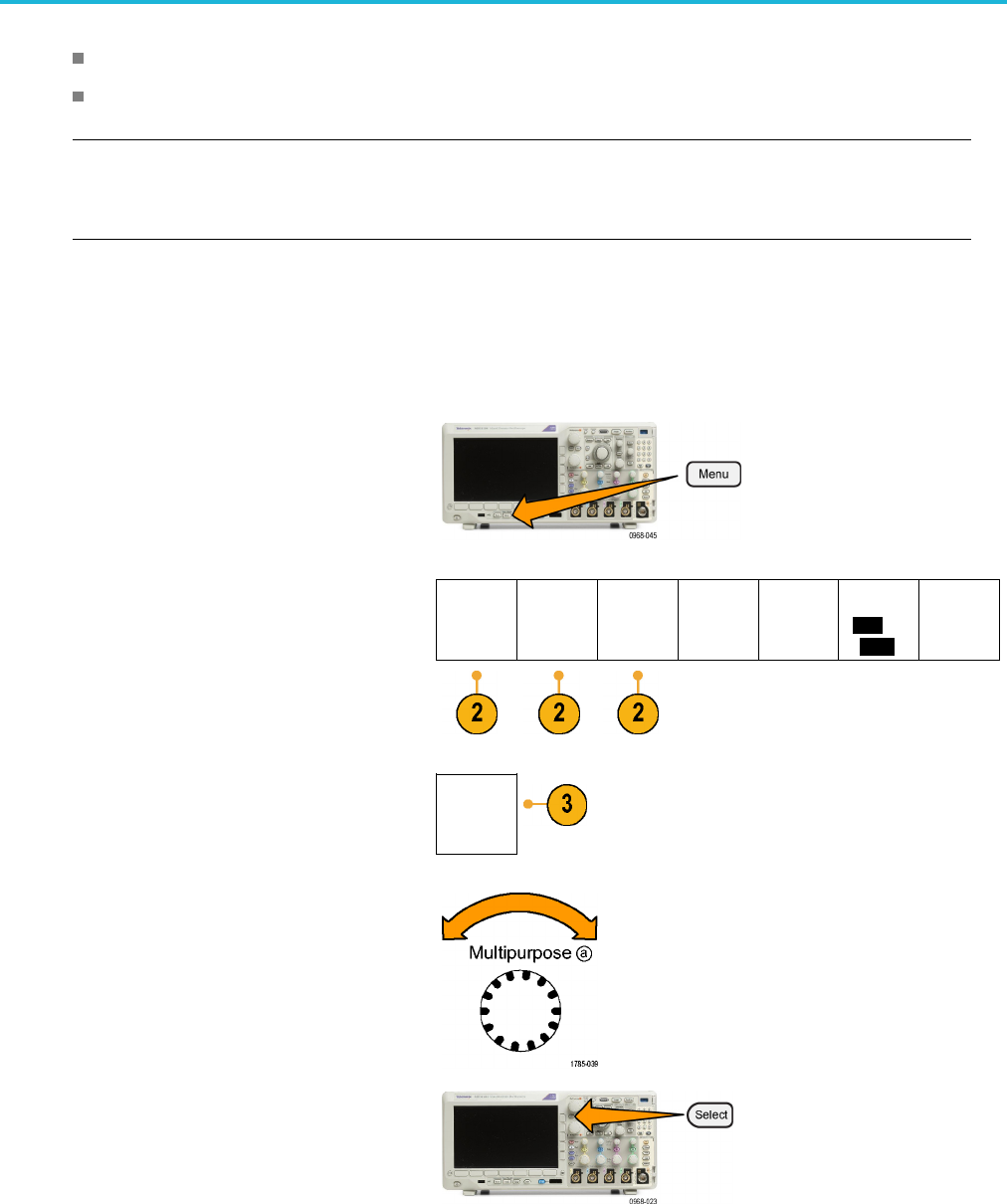
4. Turn
Multipurpose a to scroll through the
file structure. (See page 162, External file
structure.)
5. Push S elect to open or close file folders.
MDO3000 Series Oscilloscopes User Manual 163