
User Manual
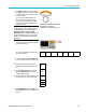
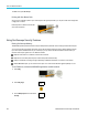
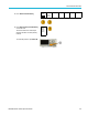
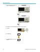
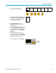
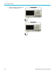
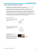
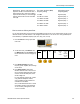
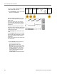
Table Of Contents
- toc
- Important safety information
- Compliance information
- Preface
- Installation
- Before Installation
- Operating Considerations
- Connecting Probes
- Securing the Oscilloscope
- Powering on the Oscilloscope
- Powering off the Oscilloscope
- Functional Check
- Compensating a TPP0250, TPP0500B or TPP1000 Passive Voltage Prob
- Compensating a non-TPP0250, non-TPP0500B or non-TPP1000 Passive
- Application Module Free Trial
- Installing an Application Module
- Upgrading Bandwidth
- Changing the Language of the User Interface or Keyboard
- Changing the Date and Time
- Signal Path Compensation
- Upgrading Firmware
- Connecting Your Oscilloscope to a Computer
- Connecting a USB Keyboard to Your Oscilloscope
- Get Acquainted with the Instrument
- Acquire the Signal
- Setting Up Analog Channels
- Using the Default Setup
- Using Autoset
- Acquisition Concepts
- Using FastAcq
- How the Analog Acquisition Modes Work
- Changing the Acquisition Mode, Record Length, and Delay Time
- Using Roll Mode
- Act on Event
- Setting Up a Serial or Parallel Bus
- Setting Up Digital Channels
- When and Why to Turn On MagniVu
- Using MagniVu
- Setting Up the RF Inputs
- Trigger Setup
- Display Waveform or Trace Data
- Adding and Removing a Waveform
- Setting the Display Style and Persistence
- Setting Waveform Intensity
- Scaling and Positioning a Waveform
- Setting Input Parameters
- Positioning and Labeling Bus Signals
- Positioning, Scaling, and Grouping Digital Channels
- Viewing Digital Channels
- Annotating the Screen
- Viewing the Trigger Frequency
- Displaying the Frequency Domain Menu
- Analyze Waveform or Trace Data
- Using Markers in the Frequency Domain
- Taking Automatic Measurements in the Time Domain
- Selecting Automatic Measurements in the Time Domain
- Customizing an Automatic Measurement in the Time Domain
- Taking Automatic Measurements in the Frequency Domain
- Taking Digital Voltmeter Measurements
- Taking Manual Measurements with Cursors
- Setting Up a Histogram
- Using Math Waveforms
- Using FFT
- Using Advanced Math
- Using Spectrum Math
- Using Reference Waveforms and Traces
- Using Wave Inspector to Manage Long Record Length Waveforms
- Auto-magnify
- Limit and Mask Testing
- Making Video Tests
- Making Automated Power Measurements
- Save and Recall Information
- Use the Arbitrary Function Generator
- Use the Application Modules
- Appendix A: Warranted Specifications
- Appendix B: TPP0250, TPP0500B and TPP1000: 250€MHz, 500€MHz and
- Appendix C: P6316 General-Purpose Logic Probe Information
- Appendix D: OpenSSL License

Use the Arbitrar
y Function G enerator
Use the Arbitr
ary Function Generator
The MDO3000 contains an optional integrated arbitrary function generator (AFG) (option MDO3AFG). This is useful for
simulating signals within a design or adding noise to signals to perform margin testing.
The function generator provides output of predefined waveforms up to 50 MHz. Choose between sine, square, pulse,
ramp/triangle, DC, noise, sin(x)/x (Sinc), Gaussian, Lorentz, exponential rise/fall, H aversine and cardiac signals.
The AFG can generate up to 131,072 points of an arbitrary waveform. You can create the waveform from any of the four
internal ARB m emories, the four (or two) analog channels, the four (or two) reference waveforms, the math waveform or the
16 digital channel waveforms. You can also use a .CSV (spreadsheet) file stored externally or a p redefined template.
You can modify your arbitrary waveform via an on-screen editor and then replicate it out of the generator. For more involved
waveform manipulation, you can use Tektronix’ ArbExpress PC-based waveform creation and editing software. It is available
for free download from www.tektronix.com/software. Use version 3.1 or later with the MDO3000.
How to acc ess the AFG
To access the AFG output, connect your cable
to the port marked AFG OUT in the back of the
oscilloscope.
To see the output of the AFG , connect the other
end of the cable to one of the input channels on
the fro
nt of the oscilloscope.
Push the front-panel AFG button to turn the
AFG output on and off.
The button lights up when the output is on. The
light goes out when it is off. The On-Off status is
always off when you recall an instrument setup.
The AFG will always come up in the off state
when you turn the oscilloscope power on.
MDO3000 Series Oscilloscopes User Manual 185