
User Manual
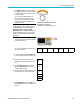
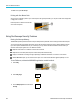
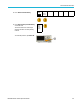
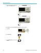
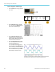
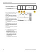
Table Of Contents
- toc
- Important safety information
- Compliance information
- Preface
- Installation
- Before Installation
- Operating Considerations
- Connecting Probes
- Securing the Oscilloscope
- Powering on the Oscilloscope
- Powering off the Oscilloscope
- Functional Check
- Compensating a TPP0250, TPP0500B or TPP1000 Passive Voltage Prob
- Compensating a non-TPP0250, non-TPP0500B or non-TPP1000 Passive
- Application Module Free Trial
- Installing an Application Module
- Upgrading Bandwidth
- Changing the Language of the User Interface or Keyboard
- Changing the Date and Time
- Signal Path Compensation
- Upgrading Firmware
- Connecting Your Oscilloscope to a Computer
- Connecting a USB Keyboard to Your Oscilloscope
- Get Acquainted with the Instrument
- Acquire the Signal
- Setting Up Analog Channels
- Using the Default Setup
- Using Autoset
- Acquisition Concepts
- Using FastAcq
- How the Analog Acquisition Modes Work
- Changing the Acquisition Mode, Record Length, and Delay Time
- Using Roll Mode
- Act on Event
- Setting Up a Serial or Parallel Bus
- Setting Up Digital Channels
- When and Why to Turn On MagniVu
- Using MagniVu
- Setting Up the RF Inputs
- Trigger Setup
- Display Waveform or Trace Data
- Adding and Removing a Waveform
- Setting the Display Style and Persistence
- Setting Waveform Intensity
- Scaling and Positioning a Waveform
- Setting Input Parameters
- Positioning and Labeling Bus Signals
- Positioning, Scaling, and Grouping Digital Channels
- Viewing Digital Channels
- Annotating the Screen
- Viewing the Trigger Frequency
- Displaying the Frequency Domain Menu
- Analyze Waveform or Trace Data
- Using Markers in the Frequency Domain
- Taking Automatic Measurements in the Time Domain
- Selecting Automatic Measurements in the Time Domain
- Customizing an Automatic Measurement in the Time Domain
- Taking Automatic Measurements in the Frequency Domain
- Taking Digital Voltmeter Measurements
- Taking Manual Measurements with Cursors
- Setting Up a Histogram
- Using Math Waveforms
- Using FFT
- Using Advanced Math
- Using Spectrum Math
- Using Reference Waveforms and Traces
- Using Wave Inspector to Manage Long Record Length Waveforms
- Auto-magnify
- Limit and Mask Testing
- Making Video Tests
- Making Automated Power Measurements
- Save and Recall Information
- Use the Arbitrary Function Generator
- Use the Application Modules
- Appendix A: Warranted Specifications
- Appendix B: TPP0250, TPP0500B and TPP1000: 250€MHz, 500€MHz and
- Appendix C: P6316 General-Purpose Logic Probe Information
- Appendix D: OpenSSL License
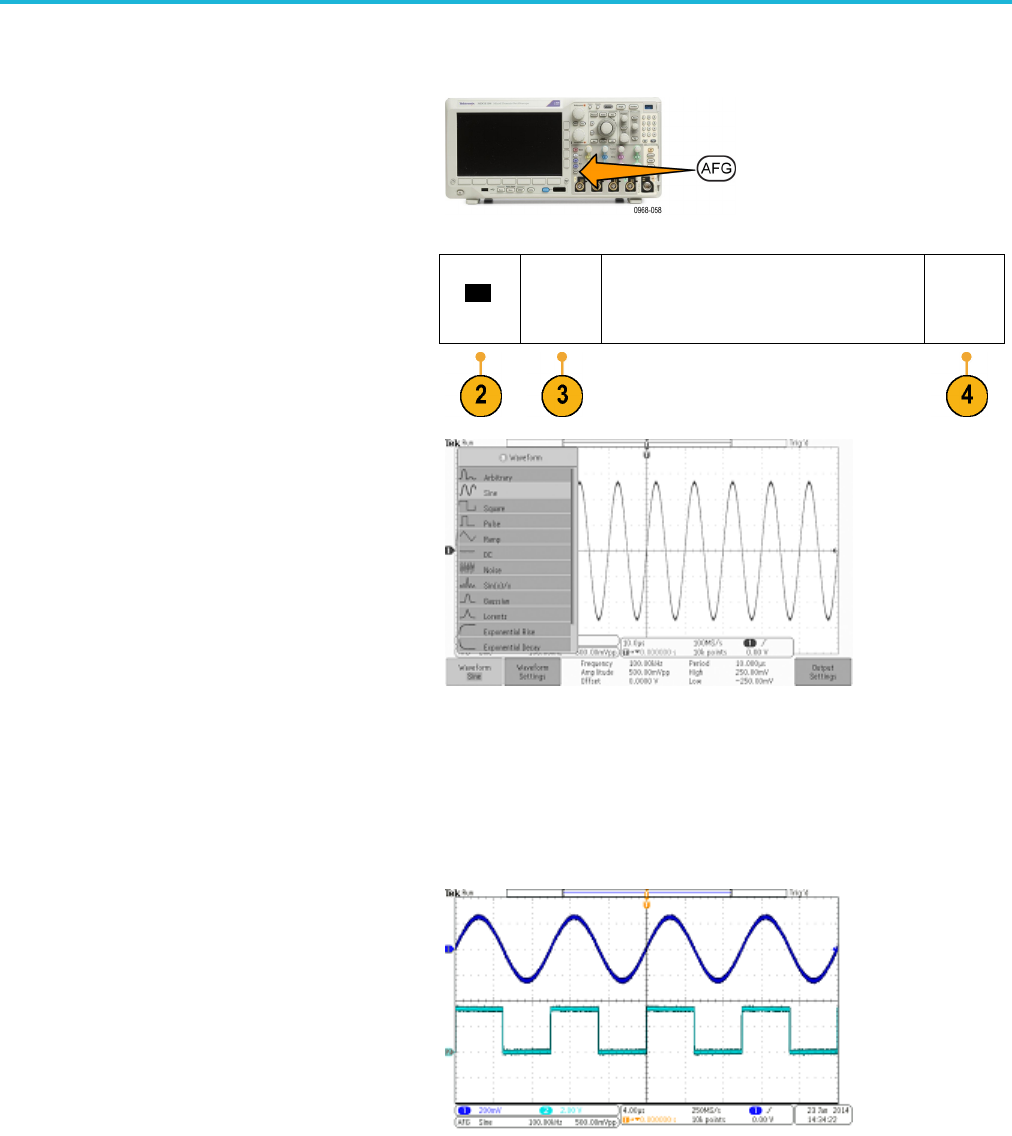
Use the Arbitrar
y Function Generator
How to change the waveform type
1. Push the AFG bu
ttontobringuptheAFG
lower menu.
Waveform
Sine
Wave–
form
Settings
Frequency
Amplitude
Offset
100.00kHz
500.00m-
Vpp
0.0000 V
Period
High
Low
10.000s
250.00mV
–250.00
mV
Output
Settings
2. Push the Waveform button on the AFG
lower menu and turn the Multipurpose a
knob to sel
ect the waveform type.
3. Push the
Waveform Settings button o n
the A FG lower menu to set the frequency,
period, amplitude, offset and the high and
low lev
els of the desired waveform.
4. Push the Output Settings buttononthe
lower m
enu to adjust the load impedance
and amount of additive noise.
You ca
n enable the AFG trigger pulse to
come out of the rear-panel AUX OUT port.
This is useful if you want an AUX OUT pulse
that
is synchronized to your AFG waveform
block. To enable this feature, push AFG >
Output Settings > AUX OUT > AFG.
The channel 1 sine wave shows the output of the A FG. The channel 2 square wave
sho
w the output of the AFG sync pulse. It comes from th e AUX OUT port.
186 MDO3000 Series Oscilloscopes User Manual