
User Manual
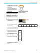
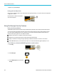
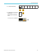
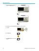
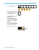
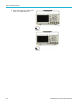
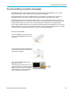
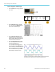
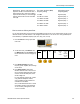
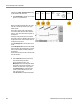
Table Of Contents
- toc
- Important safety information
- Compliance information
- Preface
- Installation
- Before Installation
- Operating Considerations
- Connecting Probes
- Securing the Oscilloscope
- Powering on the Oscilloscope
- Powering off the Oscilloscope
- Functional Check
- Compensating a TPP0250, TPP0500B or TPP1000 Passive Voltage Prob
- Compensating a non-TPP0250, non-TPP0500B or non-TPP1000 Passive
- Application Module Free Trial
- Installing an Application Module
- Upgrading Bandwidth
- Changing the Language of the User Interface or Keyboard
- Changing the Date and Time
- Signal Path Compensation
- Upgrading Firmware
- Connecting Your Oscilloscope to a Computer
- Connecting a USB Keyboard to Your Oscilloscope
- Get Acquainted with the Instrument
- Acquire the Signal
- Setting Up Analog Channels
- Using the Default Setup
- Using Autoset
- Acquisition Concepts
- Using FastAcq
- How the Analog Acquisition Modes Work
- Changing the Acquisition Mode, Record Length, and Delay Time
- Using Roll Mode
- Act on Event
- Setting Up a Serial or Parallel Bus
- Setting Up Digital Channels
- When and Why to Turn On MagniVu
- Using MagniVu
- Setting Up the RF Inputs
- Trigger Setup
- Display Waveform or Trace Data
- Adding and Removing a Waveform
- Setting the Display Style and Persistence
- Setting Waveform Intensity
- Scaling and Positioning a Waveform
- Setting Input Parameters
- Positioning and Labeling Bus Signals
- Positioning, Scaling, and Grouping Digital Channels
- Viewing Digital Channels
- Annotating the Screen
- Viewing the Trigger Frequency
- Displaying the Frequency Domain Menu
- Analyze Waveform or Trace Data
- Using Markers in the Frequency Domain
- Taking Automatic Measurements in the Time Domain
- Selecting Automatic Measurements in the Time Domain
- Customizing an Automatic Measurement in the Time Domain
- Taking Automatic Measurements in the Frequency Domain
- Taking Digital Voltmeter Measurements
- Taking Manual Measurements with Cursors
- Setting Up a Histogram
- Using Math Waveforms
- Using FFT
- Using Advanced Math
- Using Spectrum Math
- Using Reference Waveforms and Traces
- Using Wave Inspector to Manage Long Record Length Waveforms
- Auto-magnify
- Limit and Mask Testing
- Making Video Tests
- Making Automated Power Measurements
- Save and Recall Information
- Use the Arbitrary Function Generator
- Use the Application Modules
- Appendix A: Warranted Specifications
- Appendix B: TPP0250, TPP0500B and TPP1000: 250€MHz, 500€MHz and
- Appendix C: P6316 General-Purpose Logic Probe Information
- Appendix D: OpenSSL License
Use the Arbitrar
y Function G enerator
The output waveform (MHz)
frequency setting.
AFG trigger output
frequency (MHz).
4.9 MHz
Signal frequ
ency
>4.9 MHz to 14.7 MHz
Signal frequency / 3
>14.7 MHz to
24.5 MHz
Signal frequency / 5
>24.5 MHz to 34.3 MHz
Signal fre
quency / 7
>34.3 MHz to 44.1 MHz
Signal frequency / 9
Restrictions.
When an output frequency i s
higher than 4.9 MHz, some restrictions exist. A
divided frequency that is lower than 4.9 MHz is
output from th
e AUX OUT port. The AFG trigger
frequency will be limited as shown in the table
to the right.
>44.1 MHz
to 50 MHz
Signal frequency / 11
How to create an arbitrary waveform
You can create the waveform from any of the four internal ARB memories, the four (or two) analog channels, the four (or two)
reference waveforms, the math waveform or the 16 digital channel waveforms. You can also use a .CSV (spreadsheet) file
stored externally or a predefined template (square, sine, ramp, pulse, or noise).
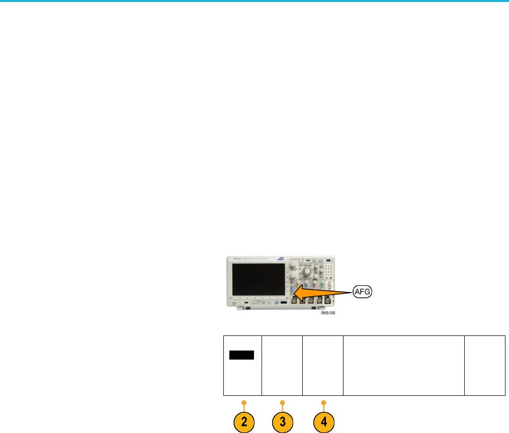
1. Push the AFG button to bring up the AFG
lower menu.
2. On the lower-menu, push Waveform and
turn M ultipurpo se a to select Arbitrary from
the list of waveforms on the resulting pop-up
menu.
Waveform
Arbitrary
Waveform
Settings
Waveform
Edit
Freq.
Ampl.
Offset
100.00kHz
500.00m-
Vpp
0.000 V
Period
10.000V
High
250.00mV
Low –250.
00mV
Output
Settings
3. Push Waveform Settings to set the
frequency, period, amplitude, offset, and high
and low levels.
4. Push Waveform Edit to bring up the
Waveform Edit lower menu. This menu will
let you manipulate existing waveform points,
as well as to add and delete points, and to
edit the voltage level.
For cases with many points to edit, consider
using Tektronix ArbExpress software,
which is available for free download from
www.tektronix.com/software.
Also, use the Waveform Edit menu to create
new arbitrary waveforms in the instrument.
You can do this by loading them from files
or from live channels.
MDO3000 Series Oscilloscopes User Manual 187