
User Manual
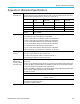
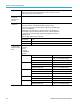
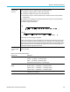
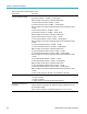
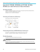
Table Of Contents
- toc
- Important safety information
- Compliance information
- Preface
- Installation
- Before Installation
- Operating Considerations
- Connecting Probes
- Securing the Oscilloscope
- Powering on the Oscilloscope
- Powering off the Oscilloscope
- Functional Check
- Compensating a TPP0250, TPP0500B or TPP1000 Passive Voltage Prob
- Compensating a non-TPP0250, non-TPP0500B or non-TPP1000 Passive
- Application Module Free Trial
- Installing an Application Module
- Upgrading Bandwidth
- Changing the Language of the User Interface or Keyboard
- Changing the Date and Time
- Signal Path Compensation
- Upgrading Firmware
- Connecting Your Oscilloscope to a Computer
- Connecting a USB Keyboard to Your Oscilloscope
- Get Acquainted with the Instrument
- Acquire the Signal
- Setting Up Analog Channels
- Using the Default Setup
- Using Autoset
- Acquisition Concepts
- Using FastAcq
- How the Analog Acquisition Modes Work
- Changing the Acquisition Mode, Record Length, and Delay Time
- Using Roll Mode
- Act on Event
- Setting Up a Serial or Parallel Bus
- Setting Up Digital Channels
- When and Why to Turn On MagniVu
- Using MagniVu
- Setting Up the RF Inputs
- Trigger Setup
- Display Waveform or Trace Data
- Adding and Removing a Waveform
- Setting the Display Style and Persistence
- Setting Waveform Intensity
- Scaling and Positioning a Waveform
- Setting Input Parameters
- Positioning and Labeling Bus Signals
- Positioning, Scaling, and Grouping Digital Channels
- Viewing Digital Channels
- Annotating the Screen
- Viewing the Trigger Frequency
- Displaying the Frequency Domain Menu
- Analyze Waveform or Trace Data
- Using Markers in the Frequency Domain
- Taking Automatic Measurements in the Time Domain
- Selecting Automatic Measurements in the Time Domain
- Customizing an Automatic Measurement in the Time Domain
- Taking Automatic Measurements in the Frequency Domain
- Taking Digital Voltmeter Measurements
- Taking Manual Measurements with Cursors
- Setting Up a Histogram
- Using Math Waveforms
- Using FFT
- Using Advanced Math
- Using Spectrum Math
- Using Reference Waveforms and Traces
- Using Wave Inspector to Manage Long Record Length Waveforms
- Auto-magnify
- Limit and Mask Testing
- Making Video Tests
- Making Automated Power Measurements
- Save and Recall Information
- Use the Arbitrary Function Generator
- Use the Application Modules
- Appendix A: Warranted Specifications
- Appendix B: TPP0250, TPP0500B and TPP1000: 250€MHz, 500€MHz and
- Appendix C: P6316 General-Purpose Logic Probe Information
- Appendix D: OpenSSL License
Appendix A: Warr
anted Specifications
Appendix A: Wa
rranted Specifications
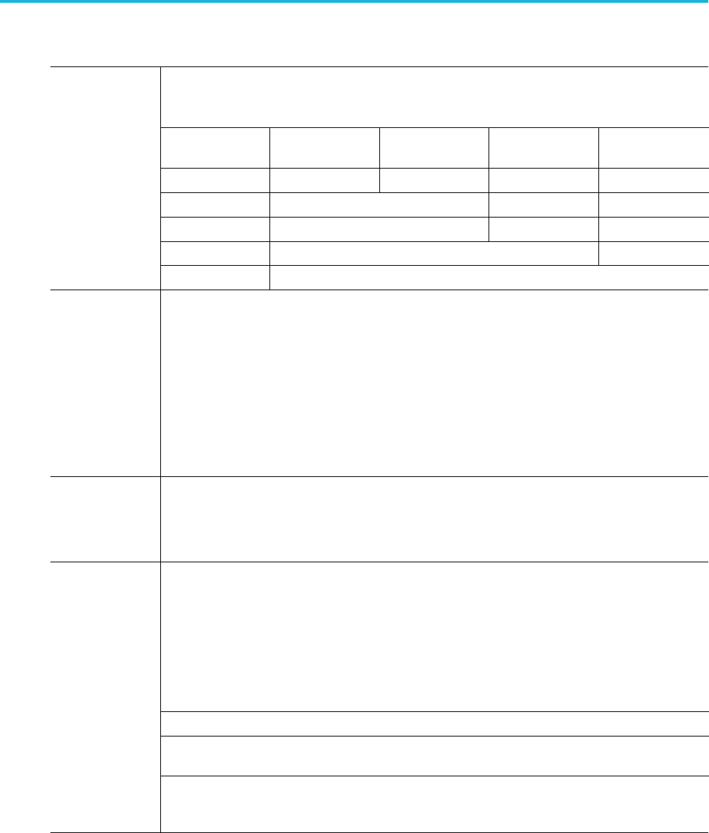
The Analog Bandwidth when the instrument is DC-50 coupled and the Bandwidth Selection if “Full”.
The limits stated below are for ambient temperature of 30 °C and the bandwidth selection set to FULL.
Reduce the upp
er bandwidth frequency by 1% for each °C above 30 °C.
Bandwidth
10 m V /div to
1V/div
5 mV/div to
9.98 mV/div
2 mV/div to
4.98 mV/div
1 mV/div to
1.99 mV/div
1 GHz DC to 1.00 GHz DC to 500 MHz DC to 300 MHz DC to 150 MHz
500 MHz
DC to 500 MHz DC to 300 MHz DC to 150 MHz
350 MHz
DC to 350 M
Hz
DC to 300 M
Hz
DC to 150 M
Hz
200 MHz
DC to 200 MHz DC to 150 MHz
Analog
bandwidth, 50
100 MHz
DC to 100 MHz
DC Bal
ance
0.2 div
with the input DC-50 coupled and 50 terminated
0.2 div with the input DC-75 coupled and 75 terminated
0.25 div at 2 mV/div with the input DC-50 coupled and 50 terminated
0.25 d
iv at 2 mV/div with the input DC-75 coupled and 75 terminated
0.5 div at 1 mV/div with the input DC-50 coupled and 50 terminated
0.5 div at 1 mV/div with the input DC-75 coupled and 75 terminated
0.2 d
iv with the input D C-1 M coupled and 50 terminated
0.3 div at 1 mV/div with the input DC-1 M coupled and 50 terminated
All above specifications are increased by (0.01 divisions)/( °C) above 40 °C
DC Gain
accuracy
±2.5% for 1 mV/div, derated at 0.100%/°C above 30 °C
±2.0% for 2 mV/div, derated at 0.100%/°C above 30 °C
±1.
5% for 5 mV/div and above, derated at 0.100%/°C above 30 °C
±3.0% variable gain, derated at 0.100%/°C above 30 ° C
Of
fset, position and the constant offset term must be converted to volts by multiplying by the appropriate
volts/div term.
The basic accuracy specification applies d irectly to any sample and to the following measurements; High,
L
ow, Max, Min, Mean, Cycle Mean, RMS, and Cycle RMS. The delta volt accuracy specification applies
to subtractive calculations invo lving two of these measurements.
The delta volts (difference voltage) accuracy specification applies directly to the following measurements;
P
ositive Overshoot, Negative Ove rshoot, Pk-Pk, and Amplitude.
The limits are as follows:
Measurement Type
DC Accuracy in Volts
Average of > 16 waveforms ±((DC Gain Accuracy) X |reading - (offset - position)| + Offset
Accuracy + 0.1 div)
D
C Voltage
Measurement
Accuracy, Average
A
cquisition mode
Delta Volts between any two averages of
16 waveforms acquired with the same
scope setup and ambient conditions
±(DC Gain Accuracy X |reading| + 0.05 div)
MDO3000 Series Oscilloscopes User Manual 193