
User Manual
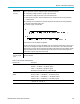
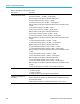
Table Of Contents
- toc
- Important safety information
- Compliance information
- Preface
- Installation
- Before Installation
- Operating Considerations
- Connecting Probes
- Securing the Oscilloscope
- Powering on the Oscilloscope
- Powering off the Oscilloscope
- Functional Check
- Compensating a TPP0250, TPP0500B or TPP1000 Passive Voltage Prob
- Compensating a non-TPP0250, non-TPP0500B or non-TPP1000 Passive
- Application Module Free Trial
- Installing an Application Module
- Upgrading Bandwidth
- Changing the Language of the User Interface or Keyboard
- Changing the Date and Time
- Signal Path Compensation
- Upgrading Firmware
- Connecting Your Oscilloscope to a Computer
- Connecting a USB Keyboard to Your Oscilloscope
- Get Acquainted with the Instrument
- Acquire the Signal
- Setting Up Analog Channels
- Using the Default Setup
- Using Autoset
- Acquisition Concepts
- Using FastAcq
- How the Analog Acquisition Modes Work
- Changing the Acquisition Mode, Record Length, and Delay Time
- Using Roll Mode
- Act on Event
- Setting Up a Serial or Parallel Bus
- Setting Up Digital Channels
- When and Why to Turn On MagniVu
- Using MagniVu
- Setting Up the RF Inputs
- Trigger Setup
- Display Waveform or Trace Data
- Adding and Removing a Waveform
- Setting the Display Style and Persistence
- Setting Waveform Intensity
- Scaling and Positioning a Waveform
- Setting Input Parameters
- Positioning and Labeling Bus Signals
- Positioning, Scaling, and Grouping Digital Channels
- Viewing Digital Channels
- Annotating the Screen
- Viewing the Trigger Frequency
- Displaying the Frequency Domain Menu
- Analyze Waveform or Trace Data
- Using Markers in the Frequency Domain
- Taking Automatic Measurements in the Time Domain
- Selecting Automatic Measurements in the Time Domain
- Customizing an Automatic Measurement in the Time Domain
- Taking Automatic Measurements in the Frequency Domain
- Taking Digital Voltmeter Measurements
- Taking Manual Measurements with Cursors
- Setting Up a Histogram
- Using Math Waveforms
- Using FFT
- Using Advanced Math
- Using Spectrum Math
- Using Reference Waveforms and Traces
- Using Wave Inspector to Manage Long Record Length Waveforms
- Auto-magnify
- Limit and Mask Testing
- Making Video Tests
- Making Automated Power Measurements
- Save and Recall Information
- Use the Arbitrary Function Generator
- Use the Application Modules
- Appendix A: Warranted Specifications
- Appendix B: TPP0250, TPP0500B and TPP1000: 250€MHz, 500€MHz and
- Appendix C: P6316 General-Purpose Logic Probe Information
- Appendix D: OpenSSL License
Appendix A: Warr
anted Specifications
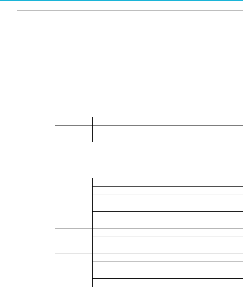
Offset accuracy
±[0.005 × | offset – position | + DC Balance]
NOTE. Both the position and constant offset term must be converted to volts by
multiplying b
y the appropriate volts/div term.
Long-term
sample rate
and delay time
accuracy
±10 ppm over any 1mstimeinterval
Selectable Output: Main Trigger, Event, or AFG
Main Trigger: HIGH to LOW transition indicates the trigger occurred.
Event Out:
The instrument will output a negative edge during a specified trigger
event in a test application.
A falling edge occurs when there is a specified event in a test application (i.e.
the wavef
orm crosses the violation threshold in the limit / mask test application).
A rising edge occurs when the trigger system begins waiting for the next test
application event.
AFG: The t
rigger output signal from the AFG.
Characteristic
Limits
Vout (HI) 2.25 V open circuit; 0.9 V into a 50 load to ground
Auxiliary output
(AUX OUT)
Vout (
LO)
0.7 V
into a load of 4mA;0.25 V into a 50 load to ground
Instrument
bandwidth
(incl
udes
instruments
with bandwidth
upgr
ades)
Bandwidth Selection RMS Noise
1GHz
Full bandwidth
<(150 V + 8% of Volts/div setting)
250
MHz bandwidth limit
<(150 V + 6% of Volts/div setting)
20 MHz bandwidth limit
<(
100 V + 4% of Volts/div setting)
Full bandwidth
<(150 V + 8% of Volts/div setting)
2
50 MHz bandwidth limit
<(150 V + 6% of Volts/div setting)
500 MHz
20 MHz bandwidth limit
<(100 V + 4% of Volts/div setting)
Full bandwidth
<(150 V + 8% of V /div setting)
250 MHz bandwidth limit
<(150 V + 6% of V /div setting)
350 MHz
20 MHz bandwidth limit
<(100 V + 4% of V /div setting)
Full bandwidth
<(150 V + 6% of Volts/div setting)
200 MHz
20 MHz bandwidth limit
<(100 V + 4% of Volts/div setting)
100 MHz Full bandwidth
<(150 V + 6% of Volts/div Setting)
Random Noise,
Sampl
e acquisition
mode
20 MHz bandwidth limit
<(100 V + 4% of Volts/div Setting)
194 MDO3000 Series Oscilloscopes User Manual