
User Manual
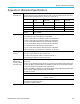
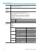
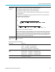
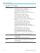
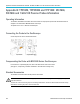
Table Of Contents
- toc
- Important safety information
- Compliance information
- Preface
- Installation
- Before Installation
- Operating Considerations
- Connecting Probes
- Securing the Oscilloscope
- Powering on the Oscilloscope
- Powering off the Oscilloscope
- Functional Check
- Compensating a TPP0250, TPP0500B or TPP1000 Passive Voltage Prob
- Compensating a non-TPP0250, non-TPP0500B or non-TPP1000 Passive
- Application Module Free Trial
- Installing an Application Module
- Upgrading Bandwidth
- Changing the Language of the User Interface or Keyboard
- Changing the Date and Time
- Signal Path Compensation
- Upgrading Firmware
- Connecting Your Oscilloscope to a Computer
- Connecting a USB Keyboard to Your Oscilloscope
- Get Acquainted with the Instrument
- Acquire the Signal
- Setting Up Analog Channels
- Using the Default Setup
- Using Autoset
- Acquisition Concepts
- Using FastAcq
- How the Analog Acquisition Modes Work
- Changing the Acquisition Mode, Record Length, and Delay Time
- Using Roll Mode
- Act on Event
- Setting Up a Serial or Parallel Bus
- Setting Up Digital Channels
- When and Why to Turn On MagniVu
- Using MagniVu
- Setting Up the RF Inputs
- Trigger Setup
- Display Waveform or Trace Data
- Adding and Removing a Waveform
- Setting the Display Style and Persistence
- Setting Waveform Intensity
- Scaling and Positioning a Waveform
- Setting Input Parameters
- Positioning and Labeling Bus Signals
- Positioning, Scaling, and Grouping Digital Channels
- Viewing Digital Channels
- Annotating the Screen
- Viewing the Trigger Frequency
- Displaying the Frequency Domain Menu
- Analyze Waveform or Trace Data
- Using Markers in the Frequency Domain
- Taking Automatic Measurements in the Time Domain
- Selecting Automatic Measurements in the Time Domain
- Customizing an Automatic Measurement in the Time Domain
- Taking Automatic Measurements in the Frequency Domain
- Taking Digital Voltmeter Measurements
- Taking Manual Measurements with Cursors
- Setting Up a Histogram
- Using Math Waveforms
- Using FFT
- Using Advanced Math
- Using Spectrum Math
- Using Reference Waveforms and Traces
- Using Wave Inspector to Manage Long Record Length Waveforms
- Auto-magnify
- Limit and Mask Testing
- Making Video Tests
- Making Automated Power Measurements
- Save and Recall Information
- Use the Arbitrary Function Generator
- Use the Application Modules
- Appendix A: Warranted Specifications
- Appendix B: TPP0250, TPP0500B and TPP1000: 250€MHz, 500€MHz and
- Appendix C: P6316 General-Purpose Logic Probe Information
- Appendix D: OpenSSL License

Appendix A: Warr
anted Specifications
Table 1 : RF Channel Characteristics (cont.)
Characteristic Description
Spurious Response (SFDR)
2
nd
harmonic distortion: >100 MHz, < –55 dBc
2nd harmonic distortion: > 100 MHz, < –60 dBc (typical)
With auto settings on and signals 10 dB below reference level
2
nd
harmonic distortion:9 kHz to 100 MHz, < –55 dBc
2
nd
harmonic distortion: 9 kHz to 100 MHz, < –60 dBc ( typical)
With auto settings on and signals 10 dB below reference level and reference level
–15 dBm
3
rd
order harmonic distortion: >100 MHz < –53 dBc
3
rd
order harmonic distortion: >100 MHz < –58 dBc (typical)
With auto settings on and signals 10 dB below reference level
3
rd
order harmonic distortion: 9 kHz to 100 MHz, < –55 dBc
3
rd
order harmonic distortion: 9 kHz to 100 MHz, < –60 dBc (typical)
With auto settings on and signals 10 dB below reference level and reference level
–15 dBm
2
nd
order intermodulation distortion: >100 Mhz, < –55 dBc
2
nd
order intermodulation distortion: >100 MHz, < –60 dBc (typical)
With auto settings on and signals 10 dB below reference level
2
nd
order intermodulation distortion: 9 k Hz to 15 MHz, < –55 dBc
2
nd
order intermodulation distortion: 9 kHz to 15 MHz, < –60 dBc (typical)
With auto settings on and signals 10 dB below reference level and reference level
–15 dBm
3
rd
order intermodulation distortion: >15 MHz, < –55 dBc
3
rd
order intermodulation distortion: >15 MHz < –60 dBc (typical)
With auto settings on and signals 10 dB below reference level
3
rd
order intermodulation distortion:9 kHz to 15 MHz, < –55 dBc
3
rd
order intermodulation distortion: 9 kHz to 15 MHz, < –60 dBc (typical)
With auto settings on and signals 10 dB below reference level and reference level
–15 dBm
–45 dBc (–50 dBc, typical) for side bands < 25 kHz offset from the carrier
Residual Spurious Response
< –78 dBm
< –67 dB m at 2.5 GHz
< –76 dBm at 1.25 GHz
–15 dBm reference level and RF input terminated with 50 .
Reference Frequency Error
(Cumulative)
Cumulative Error: ±10 x 10
-6
Includes allowances for Aging per Year, Reference Frequency Calibration Accuracy,
and Temperature Stability.
Valid over the recommended 1 year calibration interval, from –10 °C to +55 °C .
196 MDO3000 Series Oscilloscopes User Manual