
User Manual
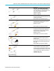
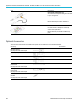

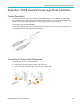
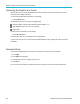

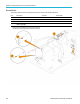
Table Of Contents
- toc
- Important safety information
- Compliance information
- Preface
- Installation
- Before Installation
- Operating Considerations
- Connecting Probes
- Securing the Oscilloscope
- Powering on the Oscilloscope
- Powering off the Oscilloscope
- Functional Check
- Compensating a TPP0250, TPP0500B or TPP1000 Passive Voltage Prob
- Compensating a non-TPP0250, non-TPP0500B or non-TPP1000 Passive
- Application Module Free Trial
- Installing an Application Module
- Upgrading Bandwidth
- Changing the Language of the User Interface or Keyboard
- Changing the Date and Time
- Signal Path Compensation
- Upgrading Firmware
- Connecting Your Oscilloscope to a Computer
- Connecting a USB Keyboard to Your Oscilloscope
- Get Acquainted with the Instrument
- Acquire the Signal
- Setting Up Analog Channels
- Using the Default Setup
- Using Autoset
- Acquisition Concepts
- Using FastAcq
- How the Analog Acquisition Modes Work
- Changing the Acquisition Mode, Record Length, and Delay Time
- Using Roll Mode
- Act on Event
- Setting Up a Serial or Parallel Bus
- Setting Up Digital Channels
- When and Why to Turn On MagniVu
- Using MagniVu
- Setting Up the RF Inputs
- Trigger Setup
- Display Waveform or Trace Data
- Adding and Removing a Waveform
- Setting the Display Style and Persistence
- Setting Waveform Intensity
- Scaling and Positioning a Waveform
- Setting Input Parameters
- Positioning and Labeling Bus Signals
- Positioning, Scaling, and Grouping Digital Channels
- Viewing Digital Channels
- Annotating the Screen
- Viewing the Trigger Frequency
- Displaying the Frequency Domain Menu
- Analyze Waveform or Trace Data
- Using Markers in the Frequency Domain
- Taking Automatic Measurements in the Time Domain
- Selecting Automatic Measurements in the Time Domain
- Customizing an Automatic Measurement in the Time Domain
- Taking Automatic Measurements in the Frequency Domain
- Taking Digital Voltmeter Measurements
- Taking Manual Measurements with Cursors
- Setting Up a Histogram
- Using Math Waveforms
- Using FFT
- Using Advanced Math
- Using Spectrum Math
- Using Reference Waveforms and Traces
- Using Wave Inspector to Manage Long Record Length Waveforms
- Auto-magnify
- Limit and Mask Testing
- Making Video Tests
- Making Automated Power Measurements
- Save and Recall Information
- Use the Arbitrary Function Generator
- Use the Application Modules
- Appendix A: Warranted Specifications
- Appendix B: TPP0250, TPP0500B and TPP1000: 250€MHz, 500€MHz and
- Appendix C: P6316 General-Purpose Logic Probe Information
- Appendix D: OpenSSL License
Appendix B: TPP0
250, TPP0500B and TPP1000: 250 MHz, 500 MHz and 1 GHz 10X Passive Probes Information
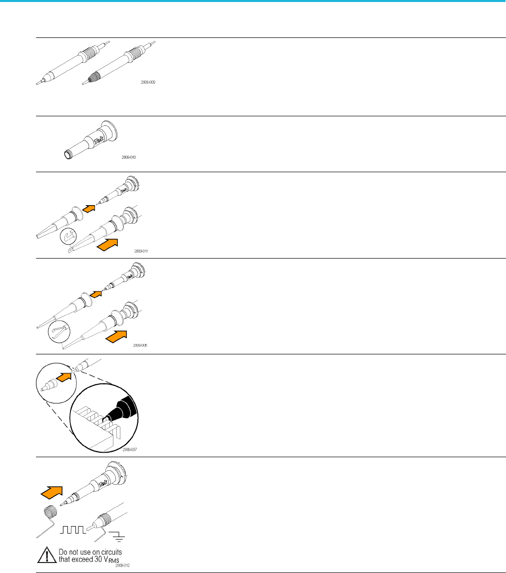
Item Description
Probe tips – pogo (white) and rigid (gray)
The white pogo
tip is pre-installed on the probe,
and is spring-loaded for compliant testing of circuit
boards. Reorder Tektronix part numbers:
206-0610-xx (
rigid tip)
206-0611-xx (pogo tip)
Insulator sl
eeve
Unscrew this sleeve to replace the probe tips. (See
procedure on next page).
Reorder Tek
tronix part number 342-1194-xx
Hook tip
Press the h
ook tip onto the probe tip and then
clamp the hook onto the circuit.
Rating: 300 V CAT II
Reorder Tektronix part number 013-0362-xx
Micro hook tip
Use this tip to access test points in tight spaces.
Press the hook tip onto the probe tip and then
extend the pincers around the circuit.
Rating: 300 V CAT II
Reorder Tektronix part number 013-0363-xx
Univer
sal IC cap
Use this cap to prevent shorting the probe tip
between IC pins.
Press
the cap on the probe tip until it snaps on, and
then spin the cap to expose the probe tip toward
the IC lead.
Reord
er Tektronix part number 013-0366-xx
Ground springs
To limit aberrations on high frequency signals
caused by ground path inductance, bend the spring
to reach nearby ground connections (<0.75 in, long;
<0.25 in, short). Reorder Tektronix part numbers:
016-2028-xx (long, 2 ea.)
016-2034-xx (short, 2 ea.)
MDO3000 Series Oscilloscopes User Manual 199