
User Manual
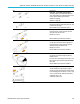
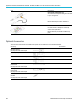

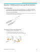
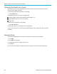

Table Of Contents
- toc
- Important safety information
- Compliance information
- Preface
- Installation
- Before Installation
- Operating Considerations
- Connecting Probes
- Securing the Oscilloscope
- Powering on the Oscilloscope
- Powering off the Oscilloscope
- Functional Check
- Compensating a TPP0250, TPP0500B or TPP1000 Passive Voltage Prob
- Compensating a non-TPP0250, non-TPP0500B or non-TPP1000 Passive
- Application Module Free Trial
- Installing an Application Module
- Upgrading Bandwidth
- Changing the Language of the User Interface or Keyboard
- Changing the Date and Time
- Signal Path Compensation
- Upgrading Firmware
- Connecting Your Oscilloscope to a Computer
- Connecting a USB Keyboard to Your Oscilloscope
- Get Acquainted with the Instrument
- Acquire the Signal
- Setting Up Analog Channels
- Using the Default Setup
- Using Autoset
- Acquisition Concepts
- Using FastAcq
- How the Analog Acquisition Modes Work
- Changing the Acquisition Mode, Record Length, and Delay Time
- Using Roll Mode
- Act on Event
- Setting Up a Serial or Parallel Bus
- Setting Up Digital Channels
- When and Why to Turn On MagniVu
- Using MagniVu
- Setting Up the RF Inputs
- Trigger Setup
- Display Waveform or Trace Data
- Adding and Removing a Waveform
- Setting the Display Style and Persistence
- Setting Waveform Intensity
- Scaling and Positioning a Waveform
- Setting Input Parameters
- Positioning and Labeling Bus Signals
- Positioning, Scaling, and Grouping Digital Channels
- Viewing Digital Channels
- Annotating the Screen
- Viewing the Trigger Frequency
- Displaying the Frequency Domain Menu
- Analyze Waveform or Trace Data
- Using Markers in the Frequency Domain
- Taking Automatic Measurements in the Time Domain
- Selecting Automatic Measurements in the Time Domain
- Customizing an Automatic Measurement in the Time Domain
- Taking Automatic Measurements in the Frequency Domain
- Taking Digital Voltmeter Measurements
- Taking Manual Measurements with Cursors
- Setting Up a Histogram
- Using Math Waveforms
- Using FFT
- Using Advanced Math
- Using Spectrum Math
- Using Reference Waveforms and Traces
- Using Wave Inspector to Manage Long Record Length Waveforms
- Auto-magnify
- Limit and Mask Testing
- Making Video Tests
- Making Automated Power Measurements
- Save and Recall Information
- Use the Arbitrary Function Generator
- Use the Application Modules
- Appendix A: Warranted Specifications
- Appendix B: TPP0250, TPP0500B and TPP1000: 250€MHz, 500€MHz and
- Appendix C: P6316 General-Purpose Logic Probe Information
- Appendix D: OpenSSL License
Appendix B: TPP0
250, TPP0500B and TPP1000: 250 MHz, 500 MHz and 1 GHz 10X Passive P robes Information
Item Description
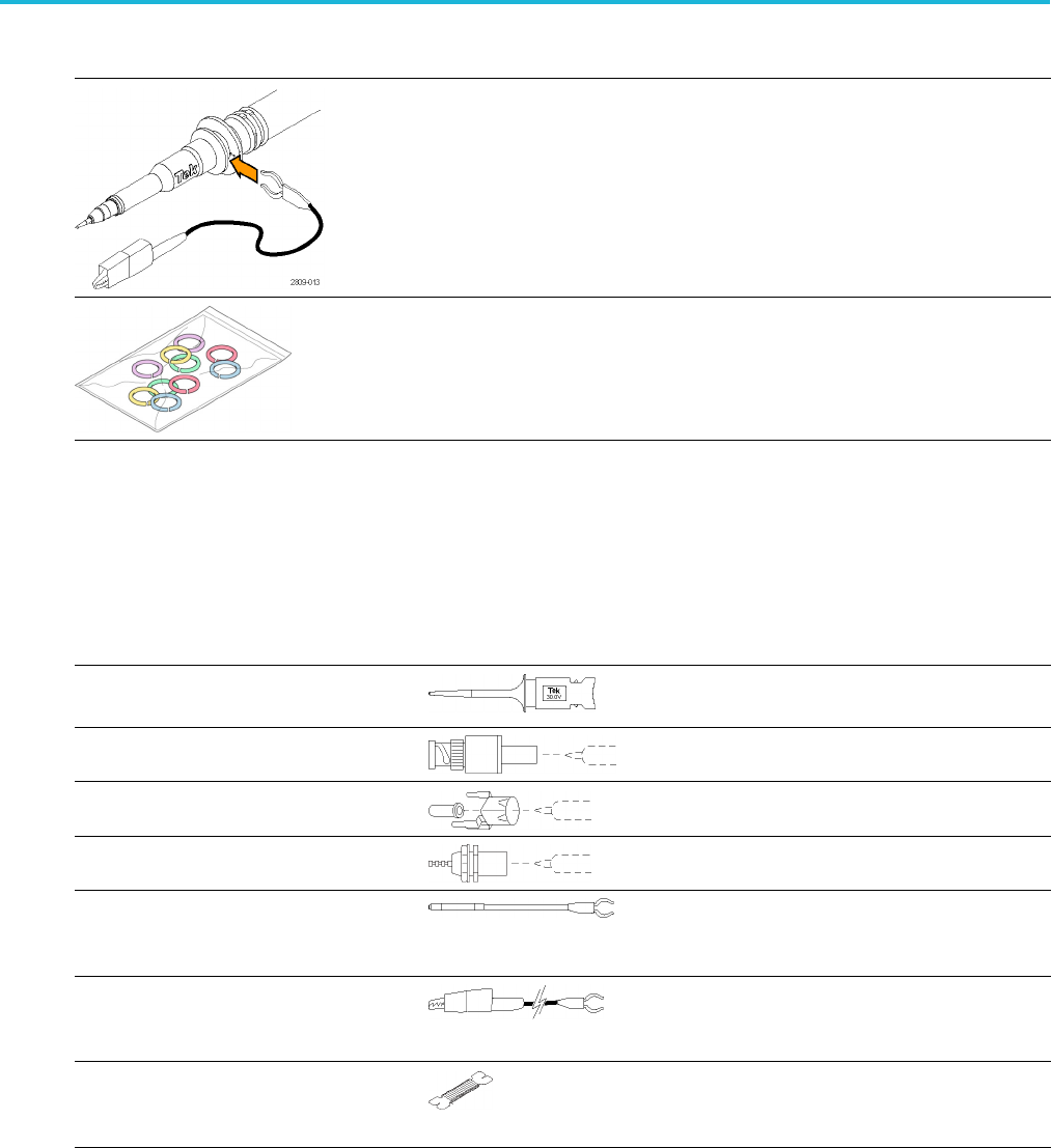
Ground lead, with alligator clip
Secure the lea
d to the probe head ground and then
to your circuit ground.
Reorder Tektronix part number 196-3521-xx
Color bands
Use these bands to identify the oscilloscope
channel at t
he probe head.
Reorder Tektronix part number 016-0633-xx (5
pairs)
Optional Accessories
The accessories shown below are available for the probes and are rated 30 V unless indicated otherwise.
Accessory Part number
MicroCKT Test Tip
One ships with each oscilloscopes
206-0569
-xx
BNC to Tip Adapter, Unterminated
013-0367-xx
Circuit Board Test Point/PCB Adapter
016-2016-xx
Chassis-Mount Probe Test Jack
131-4210-xx
6” Clip- o n
Ground Lead
One ships with each oscilloscopes
196-3198-xx
12” Alligator
Ground Lead
One ships with each oscilloscopes
196-3512-xx
Wire, s pool,
32 AW G
One ships with each oscilloscopes
020-3045-xx
200 MDO3000 Series Oscilloscopes User Manual