
User Manual
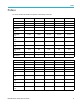


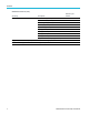

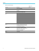
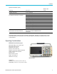
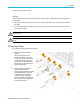
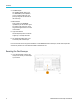
Table Of Contents
- toc
- Important safety information
- Compliance information
- Preface
- Installation
- Before Installation
- Operating Considerations
- Connecting Probes
- Securing the Oscilloscope
- Powering on the Oscilloscope
- Powering off the Oscilloscope
- Functional Check
- Compensating a TPP0250, TPP0500B or TPP1000 Passive Voltage Prob
- Compensating a non-TPP0250, non-TPP0500B or non-TPP1000 Passive
- Application Module Free Trial
- Installing an Application Module
- Upgrading Bandwidth
- Changing the Language of the User Interface or Keyboard
- Changing the Date and Time
- Signal Path Compensation
- Upgrading Firmware
- Connecting Your Oscilloscope to a Computer
- Connecting a USB Keyboard to Your Oscilloscope
- Get Acquainted with the Instrument
- Acquire the Signal
- Setting Up Analog Channels
- Using the Default Setup
- Using Autoset
- Acquisition Concepts
- Using FastAcq
- How the Analog Acquisition Modes Work
- Changing the Acquisition Mode, Record Length, and Delay Time
- Using Roll Mode
- Act on Event
- Setting Up a Serial or Parallel Bus
- Setting Up Digital Channels
- When and Why to Turn On MagniVu
- Using MagniVu
- Setting Up the RF Inputs
- Trigger Setup
- Display Waveform or Trace Data
- Adding and Removing a Waveform
- Setting the Display Style and Persistence
- Setting Waveform Intensity
- Scaling and Positioning a Waveform
- Setting Input Parameters
- Positioning and Labeling Bus Signals
- Positioning, Scaling, and Grouping Digital Channels
- Viewing Digital Channels
- Annotating the Screen
- Viewing the Trigger Frequency
- Displaying the Frequency Domain Menu
- Analyze Waveform or Trace Data
- Using Markers in the Frequency Domain
- Taking Automatic Measurements in the Time Domain
- Selecting Automatic Measurements in the Time Domain
- Customizing an Automatic Measurement in the Time Domain
- Taking Automatic Measurements in the Frequency Domain
- Taking Digital Voltmeter Measurements
- Taking Manual Measurements with Cursors
- Setting Up a Histogram
- Using Math Waveforms
- Using FFT
- Using Advanced Math
- Using Spectrum Math
- Using Reference Waveforms and Traces
- Using Wave Inspector to Manage Long Record Length Waveforms
- Auto-magnify
- Limit and Mask Testing
- Making Video Tests
- Making Automated Power Measurements
- Save and Recall Information
- Use the Arbitrary Function Generator
- Use the Application Modules
- Appendix A: Warranted Specifications
- Appendix B: TPP0250, TPP0500B and TPP1000: 250€MHz, 500€MHz and
- Appendix C: P6316 General-Purpose Logic Probe Information
- Appendix D: OpenSSL License

Installation
Optional application m odules
Tektronix p art number Description
MDO3AERO ARINC429 and MIL-STD-1553 Serial Triggering and Analysis
MDO3AUDIO Audio Serial Triggering and A nalysis (I
2
S, LJ, RJ, TDM)
MDO3AUTO Automotive Serial Triggering and Analysis (CAN, CAN FD, and LIN)
MDO3COMP Computer Serial Triggering and Analysis (RS-232, RS-422, RS-485
and UART)
MDO3EMBD Embedded S
erial Triggering and Analysis (I
2
C and SPI)
MDO3FLEX FlexRay Se
rial Triggering and Analysis
MDO3USB Universa
l Serial Bus Triggering and Analysis (LS, FS, H S).
High speed is decode only; available on 1 GHz models only.
MDO3LMT Limit/Mask Test Analysis
MDO3PWR
Power Me
asurement Analysis
Optional instrument upgrades
Tektronix p art number Description
MDO3AFG Arbitrary function generator
MDO3MSO
16 digital channels; includes P6316 digital probe
MDO3SA Increase spectrum analyzer input frequency range to 9 kHz - 3 GHz
MDO3SEC
Add password protected security to enable or disable all communication
ports and firmware upgrades to any MDO3000 Series oscilloscope.
Bandwidth upgrades
Upgrade the analog bandwidth on MDO3000 Series products
post-purchase. Visit www.tektronix.com for information o n available
upgrade products.
Optional accessories
Accessory Description
Tektronix part
number
TPA-BNC adapter TekVPI to TekProbe II BNC Adapter TPA-BNC
TPA-N-VPI adapter
Adapter from N connection (RF input) to
TekVPI probe.
TPA-N-BNC
TekVPI probes that work with MDO3000
Series oscilloscopes
Visit the Oscilloscope Probe and Accessory
Selector Tool on the Tektronix website at
www.tektronix.com/probes
—
NEX-HD2HEADER
Adapter that routes the channels from a Mictor
connector to 0.1 inch header pins
NEX-HD2HEA DER
TEK-USB-488 Adapter GPIB to USB Adapter TEK-USB-488
Rackmount kit Adds rackmount brackets RMD3000
Soft transit case
Protective front cover
Case for carrying instrument.
Also included with this case is a hard
plastic protective instrument front cover
(200-5052-00).
ACD3000
MDO3000 Series Oscilloscopes User Manual 3