
User Manual
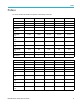


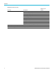

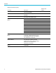
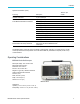
Table Of Contents
- toc
- Important safety information
- Compliance information
- Preface
- Installation
- Before Installation
- Operating Considerations
- Connecting Probes
- Securing the Oscilloscope
- Powering on the Oscilloscope
- Powering off the Oscilloscope
- Functional Check
- Compensating a TPP0250, TPP0500B or TPP1000 Passive Voltage Prob
- Compensating a non-TPP0250, non-TPP0500B or non-TPP1000 Passive
- Application Module Free Trial
- Installing an Application Module
- Upgrading Bandwidth
- Changing the Language of the User Interface or Keyboard
- Changing the Date and Time
- Signal Path Compensation
- Upgrading Firmware
- Connecting Your Oscilloscope to a Computer
- Connecting a USB Keyboard to Your Oscilloscope
- Get Acquainted with the Instrument
- Acquire the Signal
- Setting Up Analog Channels
- Using the Default Setup
- Using Autoset
- Acquisition Concepts
- Using FastAcq
- How the Analog Acquisition Modes Work
- Changing the Acquisition Mode, Record Length, and Delay Time
- Using Roll Mode
- Act on Event
- Setting Up a Serial or Parallel Bus
- Setting Up Digital Channels
- When and Why to Turn On MagniVu
- Using MagniVu
- Setting Up the RF Inputs
- Trigger Setup
- Display Waveform or Trace Data
- Adding and Removing a Waveform
- Setting the Display Style and Persistence
- Setting Waveform Intensity
- Scaling and Positioning a Waveform
- Setting Input Parameters
- Positioning and Labeling Bus Signals
- Positioning, Scaling, and Grouping Digital Channels
- Viewing Digital Channels
- Annotating the Screen
- Viewing the Trigger Frequency
- Displaying the Frequency Domain Menu
- Analyze Waveform or Trace Data
- Using Markers in the Frequency Domain
- Taking Automatic Measurements in the Time Domain
- Selecting Automatic Measurements in the Time Domain
- Customizing an Automatic Measurement in the Time Domain
- Taking Automatic Measurements in the Frequency Domain
- Taking Digital Voltmeter Measurements
- Taking Manual Measurements with Cursors
- Setting Up a Histogram
- Using Math Waveforms
- Using FFT
- Using Advanced Math
- Using Spectrum Math
- Using Reference Waveforms and Traces
- Using Wave Inspector to Manage Long Record Length Waveforms
- Auto-magnify
- Limit and Mask Testing
- Making Video Tests
- Making Automated Power Measurements
- Save and Recall Information
- Use the Arbitrary Function Generator
- Use the Application Modules
- Appendix A: Warranted Specifications
- Appendix B: TPP0250, TPP0500B and TPP1000: 250€MHz, 500€MHz and
- Appendix C: P6316 General-Purpose Logic Probe Information
- Appendix D: OpenSSL License
Installation
Optional accessories (cont.)
Accessory Description
Tektronix part
number
Hard transit case
Traveling case, which requires use of the s oft
transit case (ACD3000)
HCTEK4321
Front cover Hard plastic cover to help protect the
instrument
200-5052-00
Demonstration Board
Electronic circuit board used for demonstration
and training on the MDO3000 Series.
020-3087-XX
English 071-0968-XX
French 071-0969-XX
Italian 071-0970-XX
German
071-0971-XX
Spanish
071-0972-XX
Japanese 071-0973-XX
Portuguese 071-0974-XX
Simplified Chinese
071-0975-XX
Traditional Chinese
071-0976-XX
Korean 071-0977-XX
MDO3000 Series Oscilloscopes User
Manual
Russian 071-0978-XX
MDO3000 Series Oscilloscopes Programmer
Manual
Describes commands for remote control of the
oscilloscope. Available electronically on the
Documentation Browser CD or for download
from www.tektronix.com/manuals.
077-0510-XX
MDO3000 Series Oscilloscopes Technical
Reference Manual
Describes the oscilloscope specifications
and performance verification procedure.
Available electronically on the Documentation
Browser CD or for download from
www.tektronix.com/manuals.
077-0979-XX
MDO3000 Series Oscilloscopes Service
Manual
Service information on MDO3000 Series
oscilloscopes
077-0981-XX
4 MDO3000 Series Oscilloscopes User Manual