
User Manual
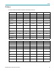


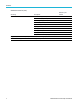

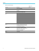
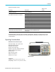
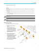
Table Of Contents
- toc
- Important safety information
- Compliance information
- Preface
- Installation
- Before Installation
- Operating Considerations
- Connecting Probes
- Securing the Oscilloscope
- Powering on the Oscilloscope
- Powering off the Oscilloscope
- Functional Check
- Compensating a TPP0250, TPP0500B or TPP1000 Passive Voltage Prob
- Compensating a non-TPP0250, non-TPP0500B or non-TPP1000 Passive
- Application Module Free Trial
- Installing an Application Module
- Upgrading Bandwidth
- Changing the Language of the User Interface or Keyboard
- Changing the Date and Time
- Signal Path Compensation
- Upgrading Firmware
- Connecting Your Oscilloscope to a Computer
- Connecting a USB Keyboard to Your Oscilloscope
- Get Acquainted with the Instrument
- Acquire the Signal
- Setting Up Analog Channels
- Using the Default Setup
- Using Autoset
- Acquisition Concepts
- Using FastAcq
- How the Analog Acquisition Modes Work
- Changing the Acquisition Mode, Record Length, and Delay Time
- Using Roll Mode
- Act on Event
- Setting Up a Serial or Parallel Bus
- Setting Up Digital Channels
- When and Why to Turn On MagniVu
- Using MagniVu
- Setting Up the RF Inputs
- Trigger Setup
- Display Waveform or Trace Data
- Adding and Removing a Waveform
- Setting the Display Style and Persistence
- Setting Waveform Intensity
- Scaling and Positioning a Waveform
- Setting Input Parameters
- Positioning and Labeling Bus Signals
- Positioning, Scaling, and Grouping Digital Channels
- Viewing Digital Channels
- Annotating the Screen
- Viewing the Trigger Frequency
- Displaying the Frequency Domain Menu
- Analyze Waveform or Trace Data
- Using Markers in the Frequency Domain
- Taking Automatic Measurements in the Time Domain
- Selecting Automatic Measurements in the Time Domain
- Customizing an Automatic Measurement in the Time Domain
- Taking Automatic Measurements in the Frequency Domain
- Taking Digital Voltmeter Measurements
- Taking Manual Measurements with Cursors
- Setting Up a Histogram
- Using Math Waveforms
- Using FFT
- Using Advanced Math
- Using Spectrum Math
- Using Reference Waveforms and Traces
- Using Wave Inspector to Manage Long Record Length Waveforms
- Auto-magnify
- Limit and Mask Testing
- Making Video Tests
- Making Automated Power Measurements
- Save and Recall Information
- Use the Arbitrary Function Generator
- Use the Application Modules
- Appendix A: Warranted Specifications
- Appendix B: TPP0250, TPP0500B and TPP1000: 250€MHz, 500€MHz and
- Appendix C: P6316 General-Purpose Logic Probe Information
- Appendix D: OpenSSL License

Installation
Humidity:
Operating:
5% to 90% relative humidity (% RH) at up to +40°C,
5% to 60% RH abo
ve +40 C up to +55°C,
non-condensing
Non-Operating:
5% to 90% RH (R
elative H umidity) at up to +40 C,
5% to 60% RH above +40°C up to +55°C,
5% to 40% RH above +55 °C up to +71 ° C
non-condens
ing
Altitude:
Operating:
3,000 m (about 9,843 ft)
Non-operating: 12,000 m (39,370 ft)
Acquisition System: 1 M
The maximum input voltage: At the BNC, 300 V
RMS
, Installation Category II. De-rate at 20 dB/decade between 4.5 MHz and
45 MHz, De
-rate 14 db between 45 MHz and 450 MHz. Above 450 MHz, 5 V
RMS
.
Acquisi
tion System: 50 and 75
The maximum input voltage: 5 V
RMS
with a peak at ±20 V. (DF 6.25%).
Dedicat
ed RF Input:
The maximum operating input level:
Average Continuous Power: +20 dBm (0.1 W)
DC maxi
mum before damage: ±40 V
DC
Max “No damage” +33 dBm (2 W) CW
Peak Pulse Power: +45 dBm (32 W)
Peak Pu
lse Power defined as <10 s pulse width, <1% duty cycle, and reference l evel of +10 dBm
CAUTI
ON. To ensure proper cooling, keep the sides and rear of the instrument clear of obstructions. Ventilation clearance
should be at least 51 mm (2 in) on the left side, when looking at the front of the instrument, and on the rear of the instrument
MDO3000 Series Oscilloscop e with a P6316 Digital Probe
Threshold Accuracy: ±(100 mV + 3% of threshold setting after calibration)
Threshold
Range: +25 V to –15 V.
Maximum nondestructive input signal to probe: +30 V to -20 V
Minimum signal swing: 500 mV
peak-to-peak
Input resistance: 101 K
Input ca
pacitance: 8.0 pF typical
Pollution Degree: 2, Indoor use only
6 MDO3000 Series Oscilloscopes User Manual