
User Manual
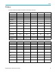


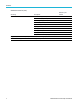

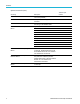
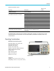
Table Of Contents
- toc
- Important safety information
- Compliance information
- Preface
- Installation
- Before Installation
- Operating Considerations
- Connecting Probes
- Securing the Oscilloscope
- Powering on the Oscilloscope
- Powering off the Oscilloscope
- Functional Check
- Compensating a TPP0250, TPP0500B or TPP1000 Passive Voltage Prob
- Compensating a non-TPP0250, non-TPP0500B or non-TPP1000 Passive
- Application Module Free Trial
- Installing an Application Module
- Upgrading Bandwidth
- Changing the Language of the User Interface or Keyboard
- Changing the Date and Time
- Signal Path Compensation
- Upgrading Firmware
- Connecting Your Oscilloscope to a Computer
- Connecting a USB Keyboard to Your Oscilloscope
- Get Acquainted with the Instrument
- Acquire the Signal
- Setting Up Analog Channels
- Using the Default Setup
- Using Autoset
- Acquisition Concepts
- Using FastAcq
- How the Analog Acquisition Modes Work
- Changing the Acquisition Mode, Record Length, and Delay Time
- Using Roll Mode
- Act on Event
- Setting Up a Serial or Parallel Bus
- Setting Up Digital Channels
- When and Why to Turn On MagniVu
- Using MagniVu
- Setting Up the RF Inputs
- Trigger Setup
- Display Waveform or Trace Data
- Adding and Removing a Waveform
- Setting the Display Style and Persistence
- Setting Waveform Intensity
- Scaling and Positioning a Waveform
- Setting Input Parameters
- Positioning and Labeling Bus Signals
- Positioning, Scaling, and Grouping Digital Channels
- Viewing Digital Channels
- Annotating the Screen
- Viewing the Trigger Frequency
- Displaying the Frequency Domain Menu
- Analyze Waveform or Trace Data
- Using Markers in the Frequency Domain
- Taking Automatic Measurements in the Time Domain
- Selecting Automatic Measurements in the Time Domain
- Customizing an Automatic Measurement in the Time Domain
- Taking Automatic Measurements in the Frequency Domain
- Taking Digital Voltmeter Measurements
- Taking Manual Measurements with Cursors
- Setting Up a Histogram
- Using Math Waveforms
- Using FFT
- Using Advanced Math
- Using Spectrum Math
- Using Reference Waveforms and Traces
- Using Wave Inspector to Manage Long Record Length Waveforms
- Auto-magnify
- Limit and Mask Testing
- Making Video Tests
- Making Automated Power Measurements
- Save and Recall Information
- Use the Arbitrary Function Generator
- Use the Application Modules
- Appendix A: Warranted Specifications
- Appendix B: TPP0250, TPP0500B and TPP1000: 250€MHz, 500€MHz and
- Appendix C: P6316 General-Purpose Logic Probe Information
- Appendix D: OpenSSL License
Installation
Humidity: 5% to 95% relative humidity
Cleaning
Inspect the oscilloscope and probes as often as operating conditions require. To clean the exterior surface, perform the
following steps:
1. Remove loose dust on the outside of the oscilloscope and probes with a lint-free cloth. Use care to avoid scratching
the display.
2. Use a soft cloth dampened with water to clean the oscilloscope. Use an aqueous solution of 75% isopropyl alcohol
for more efficient cleaning.
CAUTION. Avoid getting moisture inside the unit during external cleaning. Use only enough cleaning solution to dampen
the cloth or swab.
CAUTION. To avoid damage to the surface of the oscilloscope or probes, do not use any abrasive or c hemical cleaning
agents.
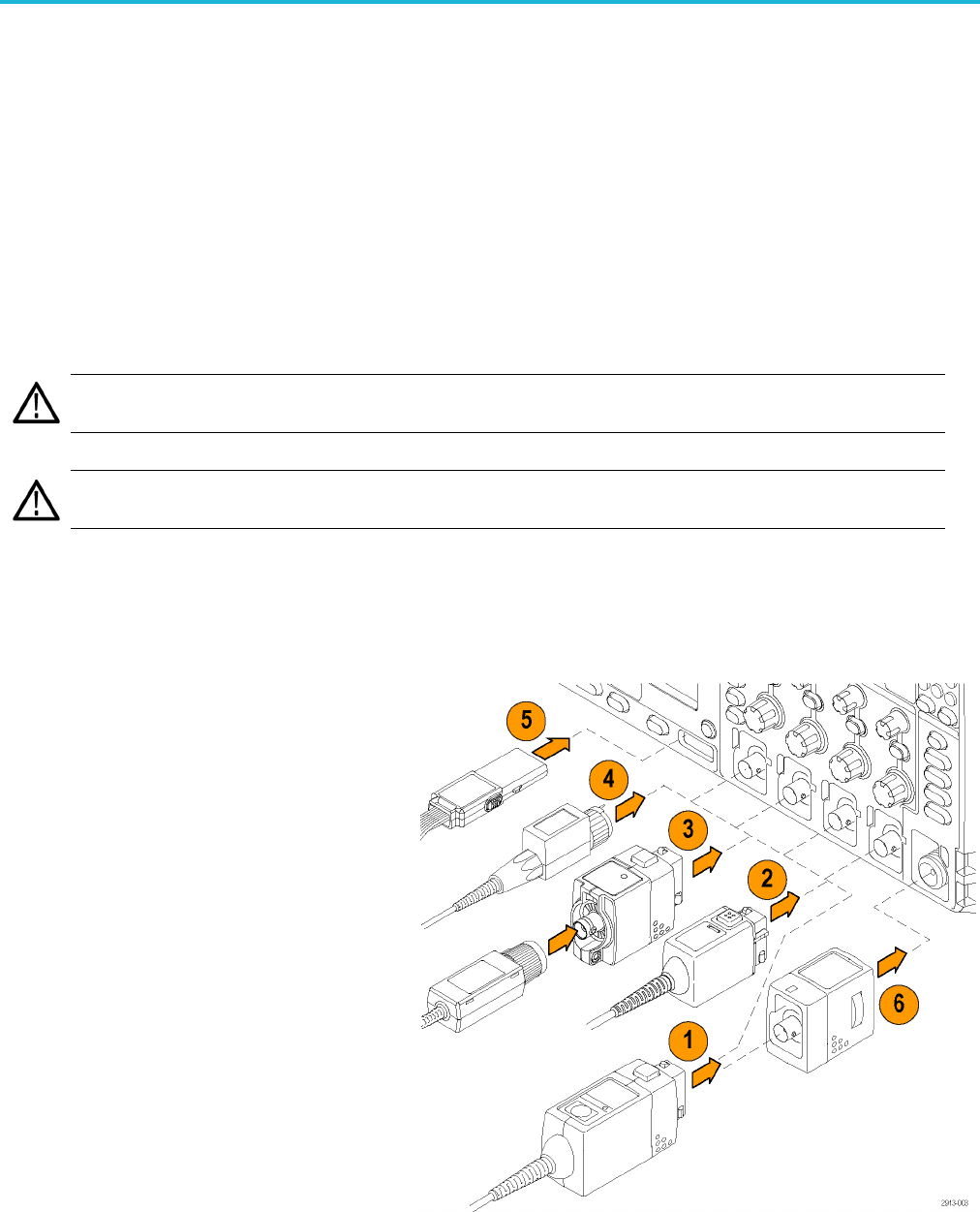
Connecting Probes
The oscilloscope supports probes with the following:
1. Tektronix Versatile Probe Interface
(TekVPI)
These probes support two-way
communication with the oscilloscope
through on-screen menus and remotely
through programmable support. The
remote control is useful in applications
like ATE where you want the system to
preset probe parameters.
2. Tektronix Versatile Probe Interface
(TekVPI) for Passive Probes
These probes build upon the functionality
of the TekVPI interface. Each probe
is matched with its corresponding
oscilloscope channel, allowing the
oscilloscope to optimize the signal input
path. This provides AC compensation
across the frequency band.
MDO3000 Series Oscilloscopes User Manual 7