
User Manual
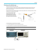
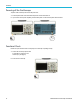
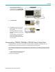
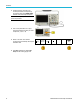
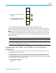
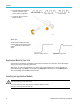
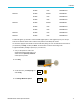
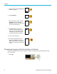
Table Of Contents
- toc
- Important safety information
- Compliance information
- Preface
- Installation
- Before Installation
- Operating Considerations
- Connecting Probes
- Securing the Oscilloscope
- Powering on the Oscilloscope
- Powering off the Oscilloscope
- Functional Check
- Compensating a TPP0250, TPP0500B or TPP1000 Passive Voltage Prob
- Compensating a non-TPP0250, non-TPP0500B or non-TPP1000 Passive
- Application Module Free Trial
- Installing an Application Module
- Upgrading Bandwidth
- Changing the Language of the User Interface or Keyboard
- Changing the Date and Time
- Signal Path Compensation
- Upgrading Firmware
- Connecting Your Oscilloscope to a Computer
- Connecting a USB Keyboard to Your Oscilloscope
- Get Acquainted with the Instrument
- Acquire the Signal
- Setting Up Analog Channels
- Using the Default Setup
- Using Autoset
- Acquisition Concepts
- Using FastAcq
- How the Analog Acquisition Modes Work
- Changing the Acquisition Mode, Record Length, and Delay Time
- Using Roll Mode
- Act on Event
- Setting Up a Serial or Parallel Bus
- Setting Up Digital Channels
- When and Why to Turn On MagniVu
- Using MagniVu
- Setting Up the RF Inputs
- Trigger Setup
- Display Waveform or Trace Data
- Adding and Removing a Waveform
- Setting the Display Style and Persistence
- Setting Waveform Intensity
- Scaling and Positioning a Waveform
- Setting Input Parameters
- Positioning and Labeling Bus Signals
- Positioning, Scaling, and Grouping Digital Channels
- Viewing Digital Channels
- Annotating the Screen
- Viewing the Trigger Frequency
- Displaying the Frequency Domain Menu
- Analyze Waveform or Trace Data
- Using Markers in the Frequency Domain
- Taking Automatic Measurements in the Time Domain
- Selecting Automatic Measurements in the Time Domain
- Customizing an Automatic Measurement in the Time Domain
- Taking Automatic Measurements in the Frequency Domain
- Taking Digital Voltmeter Measurements
- Taking Manual Measurements with Cursors
- Setting Up a Histogram
- Using Math Waveforms
- Using FFT
- Using Advanced Math
- Using Spectrum Math
- Using Reference Waveforms and Traces
- Using Wave Inspector to Manage Long Record Length Waveforms
- Auto-magnify
- Limit and Mask Testing
- Making Video Tests
- Making Automated Power Measurements
- Save and Recall Information
- Use the Arbitrary Function Generator
- Use the Application Modules
- Appendix A: Warranted Specifications
- Appendix B: TPP0250, TPP0500B and TPP1000: 250€MHz, 500€MHz and
- Appendix C: P6316 General-Purpose Logic Probe Information
- Appendix D: OpenSSL License
Installation
TPP1000
Probe
Setup
SN:
000001
Atten: 10X
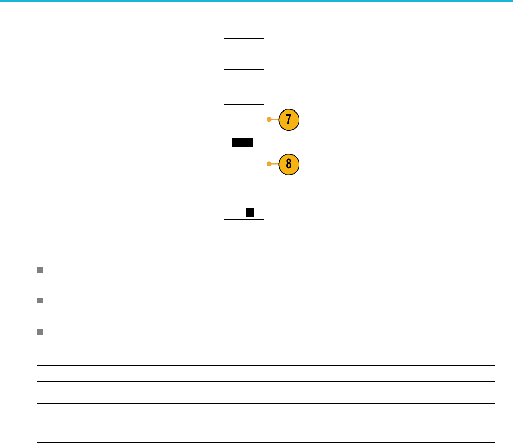
7. Notice that the compensation status starts
as Default.
Compen-
sation
Status
Default
8. Push Compens
ate p robe and follow the
instructions that appear on the display.
Compen-
sate probe
for 1
Measure
Current
Yes |
No
When compensating TPP0250/TPP0500B /TPP1000 probes on the M DO3000 Series oscilloscopes:
Each compensation generates values for a specific probe and channel combination. If you want to use the probe on
another channel and desire to compensate the new probe-channel pair, you must run a new set of compensation steps.
Each channel can store compensation values for 10 individual probes. If you try to compensate an 11th probe on a
channel, the oscilloscope will delete the values for the least recently used probe and add the values for the new probe.
The os cilloscope w
ill assign default compensation values to a TPP0250, TPP0500B or TPP1000 probe connected to
the Aux In channel.
NOTE. A factory calibration will delet e all stored compensation values
NOTE. A probe com
pensation failure is most likely due to intermittent connection of the probe tip or ground connection
during the probe compensation operation. If a failure occurs, the oscilloscope will re-use the old probe compensation values,
if they existed prior to the failed probe compensation operation.
Compensating a non-TPP0250, non -TPP0500B or non-TPP1000 Passive
Voltage Probe
Whenever you attach a passive voltage probe for the fi rst time to any input channel, compensate the probe to match it to
the corresponding oscilloscope input channel.
If you are interested in using the automatic probe compensation procedure described above for the TPP0250, TPP0500
and TPP1000 probes (See page 11, Compensating a TPP0250, TPP0500B or TPP1000 Passive Voltage Probe.). On a
non-TPP0250/TPP0500B/TPP1000 Tektronix passive probe, check the instruction manual for your probe to see if it qualifies.
Otherwise, to properly compensate your passive probe:
1. Follow the steps for the functional
check. (See page 10, Functional
Check.)
MDO3000 Series Oscilloscopes User Manual 13