
User Manual
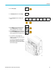
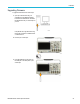
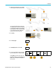
Table Of Contents
- toc
- Important safety information
- Compliance information
- Preface
- Installation
- Before Installation
- Operating Considerations
- Connecting Probes
- Securing the Oscilloscope
- Powering on the Oscilloscope
- Powering off the Oscilloscope
- Functional Check
- Compensating a TPP0250, TPP0500B or TPP1000 Passive Voltage Prob
- Compensating a non-TPP0250, non-TPP0500B or non-TPP1000 Passive
- Application Module Free Trial
- Installing an Application Module
- Upgrading Bandwidth
- Changing the Language of the User Interface or Keyboard
- Changing the Date and Time
- Signal Path Compensation
- Upgrading Firmware
- Connecting Your Oscilloscope to a Computer
- Connecting a USB Keyboard to Your Oscilloscope
- Get Acquainted with the Instrument
- Acquire the Signal
- Setting Up Analog Channels
- Using the Default Setup
- Using Autoset
- Acquisition Concepts
- Using FastAcq
- How the Analog Acquisition Modes Work
- Changing the Acquisition Mode, Record Length, and Delay Time
- Using Roll Mode
- Act on Event
- Setting Up a Serial or Parallel Bus
- Setting Up Digital Channels
- When and Why to Turn On MagniVu
- Using MagniVu
- Setting Up the RF Inputs
- Trigger Setup
- Display Waveform or Trace Data
- Adding and Removing a Waveform
- Setting the Display Style and Persistence
- Setting Waveform Intensity
- Scaling and Positioning a Waveform
- Setting Input Parameters
- Positioning and Labeling Bus Signals
- Positioning, Scaling, and Grouping Digital Channels
- Viewing Digital Channels
- Annotating the Screen
- Viewing the Trigger Frequency
- Displaying the Frequency Domain Menu
- Analyze Waveform or Trace Data
- Using Markers in the Frequency Domain
- Taking Automatic Measurements in the Time Domain
- Selecting Automatic Measurements in the Time Domain
- Customizing an Automatic Measurement in the Time Domain
- Taking Automatic Measurements in the Frequency Domain
- Taking Digital Voltmeter Measurements
- Taking Manual Measurements with Cursors
- Setting Up a Histogram
- Using Math Waveforms
- Using FFT
- Using Advanced Math
- Using Spectrum Math
- Using Reference Waveforms and Traces
- Using Wave Inspector to Manage Long Record Length Waveforms
- Auto-magnify
- Limit and Mask Testing
- Making Video Tests
- Making Automated Power Measurements
- Save and Recall Information
- Use the Arbitrary Function Generator
- Use the Application Modules
- Appendix A: Warranted Specifications
- Appendix B: TPP0250, TPP0500B and TPP1000: 250€MHz, 500€MHz and
- Appendix C: P6316 General-Purpose Logic Probe Information
- Appendix D: OpenSSL License

Installation
Connecting Your Oscilloscope to a Computer
Connect your oscilloscope directly to a computer to let the PC analyze your data, collect screen images, or to control your
oscilloscope. (See page 164, Saving a Screen Image.) (See page 165, Saving and Recalling Waveform and Trace Data.)
Three ways to connect your oscilloscope to a computer are through the VISA drivers, the e*Scope Web-enabled tools, and a
socket server. Use VISA to communicate with your oscilloscope from your computer through a software application, such as
Tektronix OpenChoice Desktop®. Use e*Scope to communicate with your oscilloscope through a Web browser, such as
Microsoft Internet E xplorer. For best results, use a browser that supports html 5.
Using VISA
VISA lets yo
u use your MS-Windows computer to acquire data from your oscilloscope for use in an analysis package that
runs on your PC, such as M icrosoft Excel, National Instruments LabVIEW, Tektronix OpenChoice Desktop software, or a
program of your own creation. You can use a common com munications connection, such as USB, Ethernet, or GPIB,
to connect
the computer to the oscilloscope.
For VISA,
load the VISA drivers on your computer. Also, load your application, such as OpenChoice Desktop. You will find
the drivers and OpenChoice Desktop software on the appropriate CD that comes with your oscilloscope or at the Tektronix
software finder Web page (www.tektronix.com).
Using e*
Scope
With e*Scope, you can access and control any Internet-connected MDO3000 Series oscilloscope from a web browser
on your computer.
Connect the oscilloscope to your network using the LAN port. The built-in LXI web interface (Core 2011, Version 1.4)
provides network configuration information, which you can edit and customize. It also provides remote instrument control
through the e*Scope user interface. There you can c ontrol instrument settings, save screen images, save instrument data or
setups, and much more. Do all this through a password-protectable web-interface.
To set up VISA communications between your oscilloscope and a computer:
1. Load the VISA drivers on your computer.
Also, load your application, such as
OpenChoice Desktop.
You will find the drivers and OpenChoice
Desktop software on the appropriate CD
that comes with your oscilloscope or at
the Tektronix software finder Web page
(www.tektronix.com).
26 MDO3000 Series Oscilloscopes User Manual