
User Manual
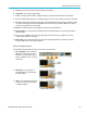
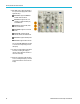
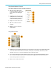
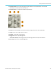
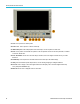

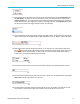
Table Of Contents
- toc
- Important safety information
- Compliance information
- Preface
- Installation
- Before Installation
- Operating Considerations
- Connecting Probes
- Securing the Oscilloscope
- Powering on the Oscilloscope
- Powering off the Oscilloscope
- Functional Check
- Compensating a TPP0250, TPP0500B or TPP1000 Passive Voltage Prob
- Compensating a non-TPP0250, non-TPP0500B or non-TPP1000 Passive
- Application Module Free Trial
- Installing an Application Module
- Upgrading Bandwidth
- Changing the Language of the User Interface or Keyboard
- Changing the Date and Time
- Signal Path Compensation
- Upgrading Firmware
- Connecting Your Oscilloscope to a Computer
- Connecting a USB Keyboard to Your Oscilloscope
- Get Acquainted with the Instrument
- Acquire the Signal
- Setting Up Analog Channels
- Using the Default Setup
- Using Autoset
- Acquisition Concepts
- Using FastAcq
- How the Analog Acquisition Modes Work
- Changing the Acquisition Mode, Record Length, and Delay Time
- Using Roll Mode
- Act on Event
- Setting Up a Serial or Parallel Bus
- Setting Up Digital Channels
- When and Why to Turn On MagniVu
- Using MagniVu
- Setting Up the RF Inputs
- Trigger Setup
- Display Waveform or Trace Data
- Adding and Removing a Waveform
- Setting the Display Style and Persistence
- Setting Waveform Intensity
- Scaling and Positioning a Waveform
- Setting Input Parameters
- Positioning and Labeling Bus Signals
- Positioning, Scaling, and Grouping Digital Channels
- Viewing Digital Channels
- Annotating the Screen
- Viewing the Trigger Frequency
- Displaying the Frequency Domain Menu
- Analyze Waveform or Trace Data
- Using Markers in the Frequency Domain
- Taking Automatic Measurements in the Time Domain
- Selecting Automatic Measurements in the Time Domain
- Customizing an Automatic Measurement in the Time Domain
- Taking Automatic Measurements in the Frequency Domain
- Taking Digital Voltmeter Measurements
- Taking Manual Measurements with Cursors
- Setting Up a Histogram
- Using Math Waveforms
- Using FFT
- Using Advanced Math
- Using Spectrum Math
- Using Reference Waveforms and Traces
- Using Wave Inspector to Manage Long Record Length Waveforms
- Auto-magnify
- Limit and Mask Testing
- Making Video Tests
- Making Automated Power Measurements
- Save and Recall Information
- Use the Arbitrary Function Generator
- Use the Application Modules
- Appendix A: Warranted Specifications
- Appendix B: TPP0250, TPP0500B and TPP1000: 250€MHz, 500€MHz and
- Appendix C: P6316 General-Purpose Logic Probe Information
- Appendix D: OpenSSL License
Get Acquainted w
ith the Instrument
5. Acquire. Push to set the acquisition mode and adjust the record length.
6. Trigger Menu. Push to specify trigger settings.
7. M. Push to manage the math waveform, including the display or removal of the math waveform from the display.
8. R. Push to manage reference waveforms, including the display or removal of each reference waveform from the display.
9. B1 or B2.Pushtodefine and display a serial bus if you have the appropriate application modules. Parallel bus support
is available
on MDO3000 products with the M DO3MSO option installed. Also, push the B1 or B2 button to display or
remove the corresponding bus from the display.
10. AFG. Push to enable the arbitrary function generator output and access the AFG menu.
11. Vertical Position. Turn to adjust the vertical position of the corresponding waveform. Push to center the waveform
baseline indicator.
12. Channel 1, 2, 3,or4Menu. Push to set vertical parameters for input waveforms and to display or remove the
correspon
ding waveform from the display.
13. Vertical S
cale. Turn to adjust the vertical scale factor of the corresponding waveform (volts/division). Push the
front-panel Fine button to make smaller adjustments.
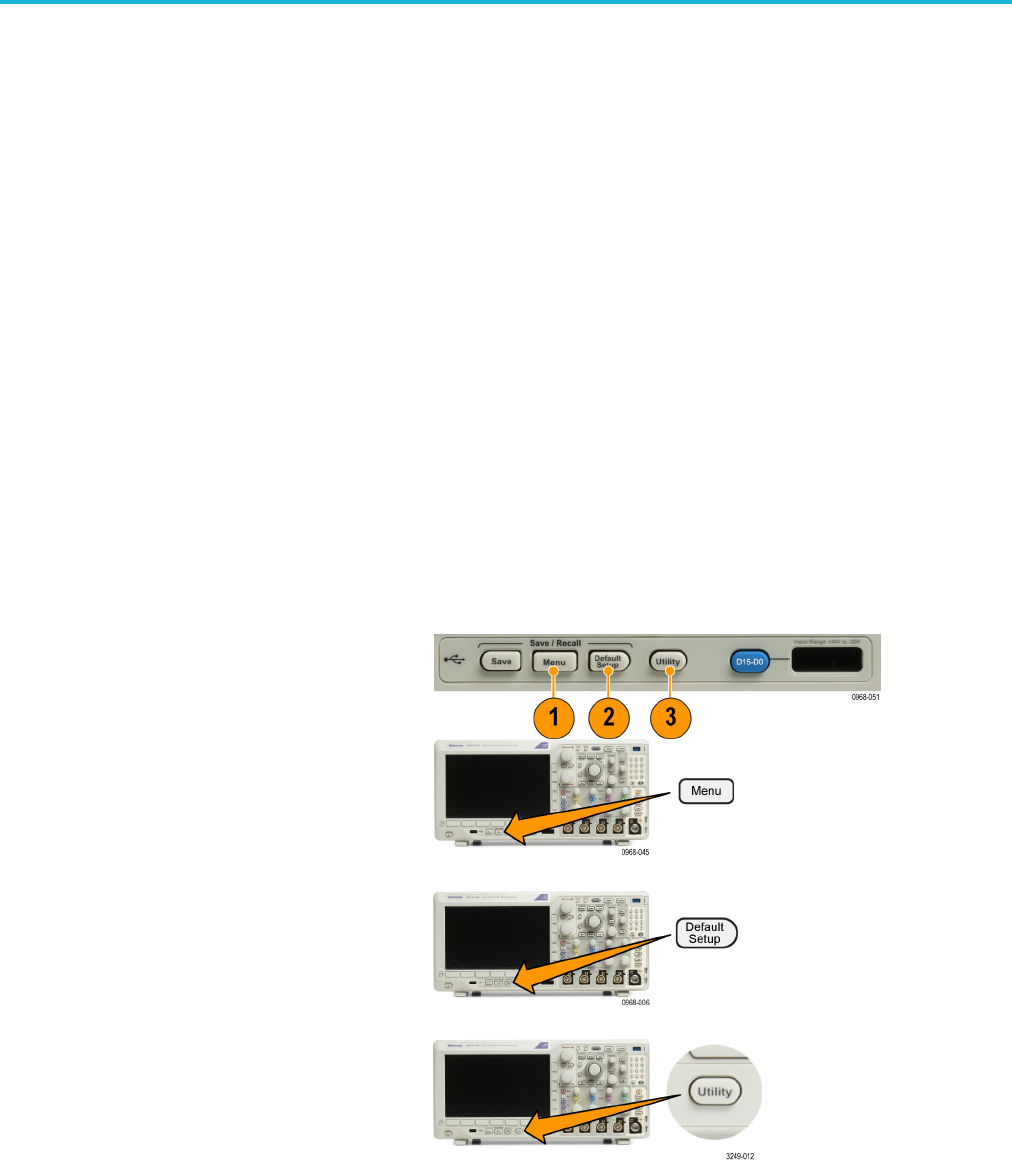
Below the display buttons
Use the buttons below the display to perform many functions in the oscilloscope.
1. Save / Re
call Menu.Pushtodefine the
Save button to save and recall setups,
waveforms, or screen images to internal
memory,
aUSBflash drive, or a mounted
network drive.
2. Default Setup. Push to perform an
immed
iate restore of the oscilloscope to
the default settings.
3. Utility. Push to activate the system utility
functions, such as selecting a language
or setting the date/time.
MDO3000 Series Oscilloscopes User Manual 39