
User Manual
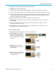
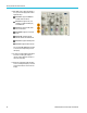
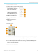
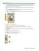
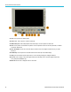

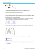
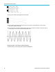
Table Of Contents
- toc
- Important safety information
- Compliance information
- Preface
- Installation
- Before Installation
- Operating Considerations
- Connecting Probes
- Securing the Oscilloscope
- Powering on the Oscilloscope
- Powering off the Oscilloscope
- Functional Check
- Compensating a TPP0250, TPP0500B or TPP1000 Passive Voltage Prob
- Compensating a non-TPP0250, non-TPP0500B or non-TPP1000 Passive
- Application Module Free Trial
- Installing an Application Module
- Upgrading Bandwidth
- Changing the Language of the User Interface or Keyboard
- Changing the Date and Time
- Signal Path Compensation
- Upgrading Firmware
- Connecting Your Oscilloscope to a Computer
- Connecting a USB Keyboard to Your Oscilloscope
- Get Acquainted with the Instrument
- Acquire the Signal
- Setting Up Analog Channels
- Using the Default Setup
- Using Autoset
- Acquisition Concepts
- Using FastAcq
- How the Analog Acquisition Modes Work
- Changing the Acquisition Mode, Record Length, and Delay Time
- Using Roll Mode
- Act on Event
- Setting Up a Serial or Parallel Bus
- Setting Up Digital Channels
- When and Why to Turn On MagniVu
- Using MagniVu
- Setting Up the RF Inputs
- Trigger Setup
- Display Waveform or Trace Data
- Adding and Removing a Waveform
- Setting the Display Style and Persistence
- Setting Waveform Intensity
- Scaling and Positioning a Waveform
- Setting Input Parameters
- Positioning and Labeling Bus Signals
- Positioning, Scaling, and Grouping Digital Channels
- Viewing Digital Channels
- Annotating the Screen
- Viewing the Trigger Frequency
- Displaying the Frequency Domain Menu
- Analyze Waveform or Trace Data
- Using Markers in the Frequency Domain
- Taking Automatic Measurements in the Time Domain
- Selecting Automatic Measurements in the Time Domain
- Customizing an Automatic Measurement in the Time Domain
- Taking Automatic Measurements in the Frequency Domain
- Taking Digital Voltmeter Measurements
- Taking Manual Measurements with Cursors
- Setting Up a Histogram
- Using Math Waveforms
- Using FFT
- Using Advanced Math
- Using Spectrum Math
- Using Reference Waveforms and Traces
- Using Wave Inspector to Manage Long Record Length Waveforms
- Auto-magnify
- Limit and Mask Testing
- Making Video Tests
- Making Automated Power Measurements
- Save and Recall Information
- Use the Arbitrary Function Generator
- Use the Application Modules
- Appendix A: Warranted Specifications
- Appendix B: TPP0250, TPP0500B and TPP1000: 250€MHz, 500€MHz and
- Appendix C: P6316 General-Purpose Logic Probe Information
- Appendix D: OpenSSL License
Get Acquainted w
ith the Instrument
Using Spectral Analysis Controls
These buttons configure the acquisition and display of the RF input.
1. RF.Pushtobri
ng up the frequency
domain display and menu. The RF menu
provides access to the Spectrogram
display.
2. Freq/Span.
Push to specify the portion
of the spectrum to view on the display.
Set the center frequency and the span –
or set the st
art and stop frequency.
3. Ampl. Push
to set the reference level.
4. BW. Push t
odefine the resolution
bandwidth.
5. Markers.
Push to set automatic or
manual markers.
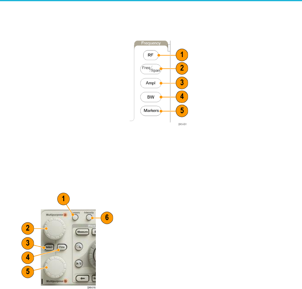
Using Other Controls
1. Cursors. Push once to activate the two vertical cursors. Push again to turn off all cursors. Push and hold to bring up the
cursor menu. Use the menu to select the cursor features, suc h as type, source, orientation, linked status, and units.
When the c ursors are on, you can turn the multipurpose knobs to control their position.
2. Turn the upper multipurpose knob a, when activated, to move a c ursor, to set a numerical parameter value for a m enu
item, or to select from a pop-out list of choices. Push the Fine button to toggle between coarse and fine adjustment.
Screen icons tell you when a or b are active.
3. S elect. Push to activate special functions.
MDO3000 Series Oscilloscopes User Manual 41