
User Manual
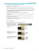
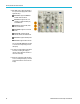
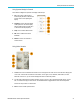
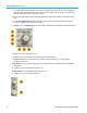
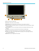

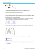
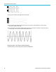
Table Of Contents
- toc
- Important safety information
- Compliance information
- Preface
- Installation
- Before Installation
- Operating Considerations
- Connecting Probes
- Securing the Oscilloscope
- Powering on the Oscilloscope
- Powering off the Oscilloscope
- Functional Check
- Compensating a TPP0250, TPP0500B or TPP1000 Passive Voltage Prob
- Compensating a non-TPP0250, non-TPP0500B or non-TPP1000 Passive
- Application Module Free Trial
- Installing an Application Module
- Upgrading Bandwidth
- Changing the Language of the User Interface or Keyboard
- Changing the Date and Time
- Signal Path Compensation
- Upgrading Firmware
- Connecting Your Oscilloscope to a Computer
- Connecting a USB Keyboard to Your Oscilloscope
- Get Acquainted with the Instrument
- Acquire the Signal
- Setting Up Analog Channels
- Using the Default Setup
- Using Autoset
- Acquisition Concepts
- Using FastAcq
- How the Analog Acquisition Modes Work
- Changing the Acquisition Mode, Record Length, and Delay Time
- Using Roll Mode
- Act on Event
- Setting Up a Serial or Parallel Bus
- Setting Up Digital Channels
- When and Why to Turn On MagniVu
- Using MagniVu
- Setting Up the RF Inputs
- Trigger Setup
- Display Waveform or Trace Data
- Adding and Removing a Waveform
- Setting the Display Style and Persistence
- Setting Waveform Intensity
- Scaling and Positioning a Waveform
- Setting Input Parameters
- Positioning and Labeling Bus Signals
- Positioning, Scaling, and Grouping Digital Channels
- Viewing Digital Channels
- Annotating the Screen
- Viewing the Trigger Frequency
- Displaying the Frequency Domain Menu
- Analyze Waveform or Trace Data
- Using Markers in the Frequency Domain
- Taking Automatic Measurements in the Time Domain
- Selecting Automatic Measurements in the Time Domain
- Customizing an Automatic Measurement in the Time Domain
- Taking Automatic Measurements in the Frequency Domain
- Taking Digital Voltmeter Measurements
- Taking Manual Measurements with Cursors
- Setting Up a Histogram
- Using Math Waveforms
- Using FFT
- Using Advanced Math
- Using Spectrum Math
- Using Reference Waveforms and Traces
- Using Wave Inspector to Manage Long Record Length Waveforms
- Auto-magnify
- Limit and Mask Testing
- Making Video Tests
- Making Automated Power Measurements
- Save and Recall Information
- Use the Arbitrary Function Generator
- Use the Application Modules
- Appendix A: Warranted Specifications
- Appendix B: TPP0250, TPP0500B and TPP1000: 250€MHz, 500€MHz and
- Appendix C: P6316 General-Purpose Logic Probe Information
- Appendix D: OpenSSL License
Get Acquainted w
ith the Instrument
11. The horizontal position/scale readout shows on the top line the horizontal scale (adjust w ith the Horizontal Scale knob).
With Delay M o de on, the bottom line shows the time from the T symbol to the expansion point icon (adjust with the
Horizontal Position knob). Use horizontal position to insert added delay between when the trigger occurs and when you
actually capture the data. Insert a negative time to capture more pretrigger information. With Delay Mode off, the bottom
line shows the time location of the trigger within the acquisition, as a percentage.
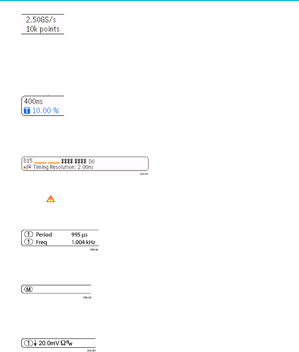
12. The Timing Resolution readout shows the timing resolution of the digital channels. Timing resolution is the time between
samples. It is the reciprocal of the digital sample rate. When the MagniVu control is on, “MagniVu” appears in the readout.
13. Measurement readouts show the selected measurements. You can select up to four measurements to d isplay at one
time. A
symbol appears instead of the expected numerical measurement if a vertical clipping condition exists. Part of
the waveform is above or below the d isplay. To obtain a proper numerical measurement, turn the vertical scale and
position knobs to make all of the waveform appear in the display.
14. The auxiliary waveform readouts show the vertical and horizontal scale factors of the math and reference waveforms.
15. The channel readout shows the channel scale factor (per division), coupling, invert , and bandwidth status. Adjust with the
Vertical Scale knob and in the channel 1, 2, 3,or4 menus.
16. For digital channels, the baseline indicators point to the high and low levels. The indicator colors follow the color code
used on resistors. The D0 indicator is black, the D1 indicator is brown, the D2 indicator is red, and so on.
MDO3000 Series Oscilloscopes User Manual 47