
User Manual
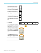
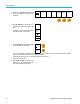
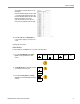
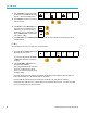
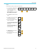

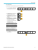
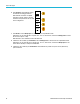
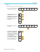
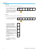
Table Of Contents
- toc
- Important safety information
- Compliance information
- Preface
- Installation
- Before Installation
- Operating Considerations
- Connecting Probes
- Securing the Oscilloscope
- Powering on the Oscilloscope
- Powering off the Oscilloscope
- Functional Check
- Compensating a TPP0250, TPP0500B or TPP1000 Passive Voltage Prob
- Compensating a non-TPP0250, non-TPP0500B or non-TPP1000 Passive
- Application Module Free Trial
- Installing an Application Module
- Upgrading Bandwidth
- Changing the Language of the User Interface or Keyboard
- Changing the Date and Time
- Signal Path Compensation
- Upgrading Firmware
- Connecting Your Oscilloscope to a Computer
- Connecting a USB Keyboard to Your Oscilloscope
- Get Acquainted with the Instrument
- Acquire the Signal
- Setting Up Analog Channels
- Using the Default Setup
- Using Autoset
- Acquisition Concepts
- Using FastAcq
- How the Analog Acquisition Modes Work
- Changing the Acquisition Mode, Record Length, and Delay Time
- Using Roll Mode
- Act on Event
- Setting Up a Serial or Parallel Bus
- Setting Up Digital Channels
- When and Why to Turn On MagniVu
- Using MagniVu
- Setting Up the RF Inputs
- Trigger Setup
- Display Waveform or Trace Data
- Adding and Removing a Waveform
- Setting the Display Style and Persistence
- Setting Waveform Intensity
- Scaling and Positioning a Waveform
- Setting Input Parameters
- Positioning and Labeling Bus Signals
- Positioning, Scaling, and Grouping Digital Channels
- Viewing Digital Channels
- Annotating the Screen
- Viewing the Trigger Frequency
- Displaying the Frequency Domain Menu
- Analyze Waveform or Trace Data
- Using Markers in the Frequency Domain
- Taking Automatic Measurements in the Time Domain
- Selecting Automatic Measurements in the Time Domain
- Customizing an Automatic Measurement in the Time Domain
- Taking Automatic Measurements in the Frequency Domain
- Taking Digital Voltmeter Measurements
- Taking Manual Measurements with Cursors
- Setting Up a Histogram
- Using Math Waveforms
- Using FFT
- Using Advanced Math
- Using Spectrum Math
- Using Reference Waveforms and Traces
- Using Wave Inspector to Manage Long Record Length Waveforms
- Auto-magnify
- Limit and Mask Testing
- Making Video Tests
- Making Automated Power Measurements
- Save and Recall Information
- Use the Arbitrary Function Generator
- Use the Application Modules
- Appendix A: Warranted Specifications
- Appendix B: TPP0250, TPP0500B and TPP1000: 250€MHz, 500€MHz and
- Appendix C: P6316 General-Purpose Logic Probe Information
- Appendix D: OpenSSL License

Acquire the Sign
al
RS-232 Bus
To acquire data from a RS-232 bus, you need to also set up these items:
1. If you selected RS-232, push Configure and
the desired side menu choices.
Bus B1
RS-232
Define
Inputs
Thresholds
Configure
9600-8-N
B1 Label
RS-232
Bus
Display
Event
Table
Use the side menu to configure the bus.
Use Normal polarity for RS-232 signals and
Inverted polarity for RS-422, RS-485, and
UART buses.
2. Push Bit Rate, and turn Multipurpo se a to
select the appropriate bit rate.
Bit Rate
9600 bps
3. Push Data Bits and select the number to
match the bus.
Data Bits
7|
8
4. Push Parity and turn Multipurpose a to
match the polarity used by the bus as None,
Odd, or Even.
Parity
(a) None
5. Push Packets and select O n or Off.
Packets
On |
Off
6. Turn Multipurpose a to select an
end-of-packet character.
End of
Packet
0A
(Linefeed)
RS-232 decoding displays a stream of bytes.
You can organize the stream into packets
with an end-of-packet character
If you defined an end-of-packet character
to use for RS-232 decoding, the stream of
bytes will be displayed as packets.
When decoding an RS-232 bus in ASCII
mode, a large dot indicates that the value
represents a character outside the printable
ASCII range.
74 MDO3000 Series Oscilloscopes User Manual