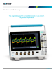
3 Series MDO Mixed Domain Oscilloscopes www.tek.
Datasheet Key performance specifications Typical applications 2 and 4 analog channel models Embedded design and IoT 100 MHz, 200 MHz, 350 MHz, 500 MHz, 1 GHz bandwidth models Up to 5 GS/s sample rate Discover and solve issues quickly by performing system level debug on mixed signal embedded systems including today's most common serial bus technologies with the 3 Series MDO and support for a broad set of common serial buses.
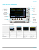
Series MDO The next generation of oscilloscopes 3 Series MDO 4 Series MSO 5 Series MSO 6 Series MSO Bandwidth up to 1 GHz up to 1.5 GHz up to 2 GHz up to 8 GHz Vertical Resolution 8 bits 12 bits 12 bits 12 bits Display 11.6" HD 13.3" HD 15.6" HD 15.6" HD Inputs TekVPI FlexChannel / TekVPI FlexChannel / TekVPI FlexChannel / TekVPI Compliance / Jitter / Windows OS Compliance / Jitter / Windows OS Advanced Analysis www.tek.
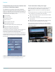
Datasheet Exceptionally easy-to-use user interface lets you focus on the task at hand The Settings Bar - key parameters and waveform management Waveform and scope operating parameters are displayed in a series of badges in the Settings Bar that runs along the bottom of the display. The Settings Bar provides immediate access for the most common waveform management tasks.
3 Series MDO Powerful Waveform Capture and Analysis At the core of the 3 Series MDO is a world-class oscilloscope, offering comprehensive tools that speed each stage of debug – from quickly discovering anomalies and capturing them, to searching your waveform record for events of interest and analyzing their characteristics and your device’s behavior. Digital phosphor technology with FastAcq™ highspeed waveform capture To debug a design problem, first you must know it exists.
Datasheet Basic waveform analysis and automated measurements Verifying that your prototype's performance matches simulations and meets the project's design goals requires careful analysis, ranging from simple checks of rise times and pulse widths to sophisticated power loss analysis, characterization of system clocks, and investigation of noise sources.
3 Series MDO Easy navigation and search Finding your event of interest in a long waveform record can be time consuming without the right search tools. With today's record lengths of many millions of data points, locating your event can mean scrolling through literally thousands of screens of signal activity. The 3 Series MDO offers the industry's most comprehensive search and waveform navigation with its innovative on-screen controls. These controls speed panning and zooming through your record.
Datasheet Comprehensive power analysis (optional) Ever increasing consumer demands for longer battery-life devices and for green solutions that consume less power require power-supply designers to characterize and minimize switching losses to improve efficiency. In addition, the supply’s power levels, output purity, and harmonic feedback into the power line must be characterized to comply with national and regional power quality standards.
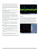
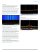
3 Series MDO Spectrogram The 3 Series MDO includes a spectrogram display which is ideal for monitoring slowly changing RF phenomena. The x-axis represents frequency, just like a typical spectrum display. However, the y-axis represents time, and color is used to indicate amplitude. Spectrogram slices are generated by taking each spectrum and "flipping it up on its edge" so that it's one pixel row tall, and then assigning colors to each pixel based on the amplitude at that frequency.
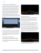
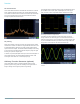
Datasheet RF measurements The 3 Series MDO includes three automated RF measurements - Channel Power, Adjacent Channel Power Ratio, and Occupied Bandwidth. When one of these RF measurements is activated, the oscilloscope automatically turns on the Average spectrum trace and sets the detection method to Average for optimal measurement results.
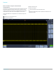
3 Series MDO Digital Channels (optional) The logic analyzer (option 3-MSO) provides 16 digital channels which are tightly integrated into the oscilloscope's user interface. This simplifies operation and makes it possible to solve mixed-signal issues easily. Once a group is formed, you can position all the channels contained in that group collectively.
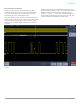
Datasheet Serial Protocol Triggering and Analysis (optional) On a serial bus, a single signal often includes address, control, data, and clock information. This can make isolating events of interest difficult. Automatic trigger, decode, and search on bus events and conditions gives you a robust set of tools for debugging serial buses. The optional serial protocol triggering and analysis functionality is offered free for a 30-day trial period.
3 Series MDO Search (serial triggering) Connectivity Serial triggering is very useful for isolating the event of interest, but once you’ve captured it and need to analyze the surrounding data, what do you do? In the past, users had to manually scroll through the waveform counting and converting bits and looking for what caused the event. You can have the oscilloscope automatically search through the acquired data for user-defined criteria including serial packet content.
Datasheet TekVPI probe interface The TekVPI probe interface sets the standard for ease of use in probing. In addition to the secure, reliable connection that the interface provides, TekVPI probes feature status indicators and controls, as well as a probe menu button right on the comp box itself. This button brings up a probe menu on the oscilloscope display with all relevant settings and controls for the probe.
3 Series MDO Specifications All specifications are guaranteed unless noted otherwise. All specifications apply to all models unless noted otherwise. MDO32 and MDO34 Analog channel bandwidth 100 MHz 100 MHz 200 MHz 200 MHz 350 MHz 350 MHz 500 MHz 500 MHz 1 GHz 1 GHz Analog channels 2 4 2 4 2 4 2 4 2 4 Rise time (typical, calculated) (10 mV/div setting with 50 Ω input termination) 4 ns 4 ns 2 ns 2 ns 1.14 ns 1.14 ns 800 ps 800 ps 400 ps 400 ps Sample rate (1 ch) 2.5 GS/s 2.
Datasheet Vertical system analog channels Maximum input voltage 1 MΩ 300 VRMS CAT II with peaks ≤ ±425 V 50 Ω 5 VRMS with peaks ≤ ±20 V DC gain accuracy ±1.5% for 5 mV/div and above, derated at 0.10%/°C above 30 °C ±2.0% for 2 mV/div, derated at 0.10%/°C above 30 °C ±2.5% for 1 mV/div, derated at 0.10%/°C above 30 °C ±3.0% for variable gain, derated 0.
3 Series MDO Trigger system Trigger modes Auto, Normal, and Single Trigger coupling DC, AC, HF reject (attenuates >50 kHz), LF reject (attenuates <50 kHz), noise reject (reduces sensitivity) Trigger holdoff range 20 ns to 8 s Trigger sensitivity (typical) Edge type, DC coupled Trigger source Sensitivity Any analog channel input For 1 mV/div to 4.98 mV/div; 0.75 div from DC to 50 MHz, increasing to 1.3 div at instrument bandwidth ≥ 5 mV/div: 0.
Datasheet Acquisition system Acquisition modes Sample Acquire sampled values. Peak Detect Captures glitches as narrow as 1.5 ns (1 GHz models), 2.0 ns (500 MHz models), 3.0 ns (350 MHz models), 5.0 ns (200 MHz models), 7.0 ns (100 MHz models) at all sweep speeds Averaging From 2 to 512 waveforms included in average. Envelope Min-max envelope reflecting Peak Detect data over multiple acquisitions.
3 Series MDO Act on Event Events None, when a trigger occurs, or when a defined number of acquisitions complete (1 to 1,000,000) Actions Stop acquisition, save waveform to file, save screen image, print, AUX OUT pulse, remote interface SRQ, e-mail notification, and visual notification Repeat Repeat the act on event process (1 to 1,000,000 and infinity) Power measurements (optional) Power quality measurements VRMS, VCrest Factor, Frequency, IRMS, ICrest Factor, True Power, Apparent Power, Reactive Pow
Datasheet DANL with TPA-N-PRE preamp attached Preamp set to "Auto", and Reference Level set to -40 dB 9 kHz - 50 kHz < -117 dBm/Hz (< -121 dBm/Hz typical) 50 kHz – 5 MHz < -136 dBm/Hz (< -140 dBm/Hz typical) 5 MHz - 2 GHz < -146 dBm/Hz (< -150 dBm/Hz typical) 2 GHz – 3 GHz < -136 dBm/Hz (< -140 dBm/Hz typical) Spurious response 2nd harmonic distortion (>100 MHz) < -55 dBc (< -60 dBc typical) 3rd harmonic distortion (>100 MHz) < -53 dBc (< -58 dBc typical) 2nd order intermodulation distortion (
3 Series MDO Maximum power before damage (CW) +33 dBm (2 W) Maximum power before damage (pulse) +45 dBm (32 W) (<10 µs pulse width, <1% duty cycle, and reference level of ≥ +10 dBm) Maximum operating input level with TPA-N-PRE preamp attached Average continuous power +20 dBm (0.
Datasheet Arbitrary Function Generator (Requires 3-AFG option) Waveforms Sine, Square, Pulse, Ramp/Triangle, DC, Noise, Sin(x)/x (Sinc), Gaussian, Lorentz, Exponential Rise, Exponential Decay, Haversine, Cardiac, and Arbitrary. Sine Frequency range 0.1 Hz to 50 MHz Amplitude range 20 mVp-p to 5 Vp-p into Hi-Z; 10 mVp-p to 2.5 Vp-p into 50 Ω Amplitude flatness (typical) ±0.5 dB at 1 kHz (±1.
3 Series MDO Lorentz Frequency range (typical) 0.1 Hz to 5 MHz Amplitude range 20 mVp-p to 2.4 Vp-p into Hi-Z; 10 mVp-p to 1.2 Vp-p into 50 Ω Exponential Rise / Decay Frequency range (typical) 0.1 Hz to 5 MHz Amplitude range 20 mVp-p to 2.5 Vp-p into Hi-Z; 10 mVp-p to 1.25 Vp-p into 50 Ω Haversine Frequency range (typical) 0.1 Hz to 5 MHz Amplitude range 20 mVp-p to 2.5 Vp-p into Hi-Z; 10 mVp-p to 1.25 Vp-p into 50 Ω Cardiac (typical) Frequency range 0.
Datasheet Logic Analyzer (Requires 3-MSO option) Vertical system digital channels Input channels 16 digital (D15 to D0) Thresholds Threshold per set of 8 channels Threshold selections TTL, CMOS, ECL, PECL, User-defined User-defined threshold range -15 V to +25 V Maximum input voltage -20 V to +30 V Threshold accuracy ±[130mV + 3% of threshold setting] Input dynamic range 50 Vp-p (threshold setting dependent) Minimum voltage swing 500 mV Input resistance 101 kΩ Probe loading 8 pF Vertic
3 Series MDO Serial Protocol Analyzer Automated Serial Triggering, Decode, and Search options for I2C, SPI, RS-232/422/485/UART, USB2.0, CAN, CAN FD (ISO and non-ISO), LIN, FlexRay, MIL-STD-1553, ARINC429, and Audio buses. For more detailed information about serial bus support products please see the Serial Triggering and Analysis datasheet. Trigger types I2C (optional) Trigger on Start, Repeated Start, Stop, Missing ACK, Address (7 or 10 bit), Data, or Address and Data on I2C buses up to 10 Mb/s.
Datasheet Digital Voltmeter (Free with product registration) Source Channel 1, Channel 2, Channel 3, Channel 4 Measurement types ACrms, DCrms, AC+DCrms (reads out in volts or amps); frequency count Resolution Voltage: 4 digits Frequency: 5 digits Frequency accuracy ±(10 µHz/Hz + 1 count) Measuring rate 100 times/second; measurements updated on the display 4 times/second Vertical settings autorange Automatic adjustment of vertical settings to maximize measurement dynamic range; available for any
3 Series MDO Input/output ports USB 2.0 high-speed host port Supports USB mass storage devices and keyboard. Two ports on front and one port on rear of instrument. USB 2.0 device port Rear-panel connector allows for communication/control of oscilloscope through USBTMC or GPIB (with a TEK-USB-488). Printing Print to network printer or to a printer that supports e-mail printing. Note: This product includes software developed by the OpenSSL Project for use in the OpenSSL Toolkit. (http://www.openssl.
Datasheet Power source Power source voltage 100 to 240 V ±10% Power source frequency 50 to 60 Hz at 100 to 240 V 400 Hz ±10% at 115 V Power consumption 130 W maximum Physical characteristics Dimensions Height 252 mm (9.93 in.) Width 370 mm (14.57 in.) Depth 148.6 mm (5.85 in.) Weight Net MDO34 1GHz: 11.7 lbs (5.31 kg) MDO32 1GHz: 11.6 lbs (5.26 kg) Shipping 17.4 lbs (7.89 kg) Rackmount configuration 6U Cooling clearance 2 in. (50.
3 Series MDO Random vibration Non-operating: 2.46 GRMS, 5-500 Hz, 10 minutes per axis, 3 axes, 30 minutes total Operating: 0.
Datasheet Step 2 Configure your 3 Series MDO by adding options Instrument options All 3 Series MDO instruments can be preconfigured from the factory with the following options: 3-AFG Arbitrary function generator with 13 predefined waveforms and arbitrary waveform generation. 3-MSO 16 digital channels; includes P6316 digital probe and accessories. 3-SA1 Spectrum analyzer; frequency range from 9 kHz to 1 GHz and capture bandwidth to 1 GHz.
3 Series MDO Service options Opt. C3 Calibration Service 3 Years Opt. C5 Calibration Service 5 Years Opt. D1 Calibration Data Report Opt. D3 Calibration Data Report 3 Years (with Opt. C3) Opt. D5 Calibration Data Report 5 Years (with Opt. C5) Opt. R5 Repair Service 5 Years (including warranty) Opt.
Datasheet THDP0200 ±1.5 kV, 200 MHz TekVPI® high-voltage differential probe TMDP0200 ±750 V, 200 MHz TekVPI® high-voltage differential probe TIVM1 / L Isolated Probe; 1 GHz, ±50 V, TekVPI, 10 Meter Cable P6246 400 MHz differential active FET probe (Level II TekProbe) P6427 1 GHz differential active FET probe (Level II TekProbe) P5100 2.
3 Series MDO 101A EMC probe set 150A EMC probe amplifier 110A Probe cable 0309-0001 SMA probe adapter 0309-0006 BNC probe adapter Future instrument upgrades after purchase Instrument upgrades The 3 Series MDO products offer a number of ways to add functionality after the initial purchase. Listed below are the various product upgrades available and the method of upgrade used for each product.
Datasheet Bandwidth upgrade options Instrument bandwidth can be upgraded on any 3 Series MDO product after initial purchase. Each upgrade product increases analog bandwidth and spectrum analyzer frequency range. Bandwidth upgrades are purchased based on the combination of the current bandwidth and the desired bandwidth. Software option key products depend on instrument model and serial number combination.
3 Series MDO www.tek.
Datasheet ASEAN / Australasia (65) 6356 3900 Belgium 00800 2255 4835* Central East Europe and the Baltics +41 52 675 3777 Finland +41 52 675 3777 Hong Kong 400 820 5835 Japan 81 (3) 6714 3086 Middle East, Asia, and North Africa +41 52 675 3777 People's Republic of China 400 820 5835 Republic of Korea +822 6917 5084, 822 6917 5080 Spain 00800 2255 4835* Taiwan 886 (2) 2656 6688 Austria 00800 2255 4835* Brazil +55 (11) 3759 7627 Central Europe & Greece +41 52 675 3777 France 00800 2255 4835* India 000 800 6