
Data Sheet


Serial Protocol Triggering and Analysis
(optional)
On a serial bus, a single signal often includes address, control, data, and
clock information. This can make isolating events of interest difficult.
Automatic trigger, decode, and search on bus events and conditions gives
you a robust set of tools for debugging serial buses. The optional serial
protocol triggering and analysis functionality is offered free for a 30-day trial
period. This free trial period starts automatically when the instrument is
powered on for the first time.
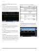
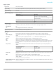
Triggering on a specific address and data packet going across an I
2
C bus. The yellow
waveform is clock and the blue waveform is the data. A bus waveform provides decoded
packet content including Start, Address, Read/Write, Data, and Stop.
Serial triggering
Trigger on packet content such as start of packet, specific addresses,
specific data content, unique identifiers, etc. on popular serial interfaces
such as I
2
C, SPI, RS-232/422/485/UART, USB2.0, CAN, CAN FD, LIN,
FlexRay, MIL-STD-1553, ARINC429, and I
2
S/LJ/RJ/TDM.
Bus display
Provides a higher-level, combined view of the individual signals (clock,
data, chip enable, etc.) that make up your bus, making it easy to identify
where packets begin and end and identifying sub-packet components such
as address, data, identifier, CRC, etc.
Bus decoding
Tired of having to visually inspect the waveform to count clocks, determine
if each bit is a 1 or a 0, combine bits into bytes, and determine the hex
value? Let the oscilloscope do it for you! Once you’ve set up a bus, the
3 Series MDO will decode each packet on the bus, and display the value in
hex, binary, decimal (USB, CAN, CAN FD, LIN, FlexRay, MIL-STD-1553,
and ARINC429 only), signed decimal (I
2
S/LJ/RJ/TDM only), or ASCII (USB,
MIL-STD-1553 and RS-232/422/485/UART only) in the bus waveform.
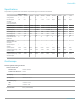
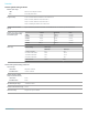
Serial bus technologies supported by the 3 Series MDO
Technology Trigger, Decode,
Search
Order product
Embedded I
2
C Yes 3-SREMBD
SPI Yes 3-SREMBD
Computer RS232/422/485,
UART
Yes 3-SRCOMP
USB USB LS, FS, HS Yes (trigger on LS
and FS only; HS
decode only on
1 GHz models)
3-SRUSB2
Automotive CAN, CAN FD Yes 3-SRAUTO
LIN Yes 3-SRAUTO
FlexRay Yes 3-SRAUTO
Military and
Aerospace
MIL-STD-1553,
ARINC429
Yes 3-SRAERO
Audio I
2
S Yes 3-SRAUDIO
LJ, RJ Yes 3-SRAUDIO
TDM Yes 3-SRAUDIO
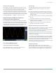
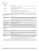
Event table
In addition to seeing decoded packet data on the bus waveform itself, you
can view all captured packets in a tabular view much like you would see in
a software listing. Packets are time stamped and listed consecutively with
columns for each component (Address, Data, etc.). You can save the event
table data in .CSV format.
Event table showing decoded identifier, DLC, DATA, and CRC for every CAN packet in a
long acquisition.
Datasheet
12 www.tek.com