4 Series MSO Mixed Signal Oscilloscope Datasheet www.tek.
Datasheet Strength in numbers Input channels ® 4 or 6 FlexChannel inputs Each FlexChannel provides: One analog signal that can be displayed as a waveform view, a spectrum view 1, or both simultaneously Eight digital logic inputs with TLP058 logic probe Bandwidth (all analog channels) 200 MHz, 350 MHz, 500 MHz, 1 GHz, 1.5 GHz (upgradable) Sample rate (all analog / digital channels) Real-time: 6.25 GS/s Record length (all analog / digital channels) 31.25 Mpoints standard (62.
4 Series MSO Never let a lack of channels slow down your verification and debug process again! The 4 Series MSO offers better visibility into complex systems by offering four and six channel models with a 13.3-inch high-definition (1,920 x 1,080) display.
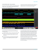
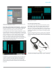
Datasheet Channel 2 has a TLP058 Logic Probe connected to the eight inputs of a DAC. Notice the green and blue color coding, where ones are green and zeros are blue. Another TLP058 Logic Probe on Channel 3 is probing the SPI bus driving the DAC. The white edges indicate higher frequency information is available by either zooming in or moving to a faster sweep speed on the next acquisition. Beyond just analog and digital, FlexChannel inputs include Spectrum View.
4 Series MSO Unprecedented signal viewing capability The stunning 13.3-inch (338 mm) display in the 4 Series MSO is the largest display in its class. It is also the highest resolution display, with full HD resolution (1,920 x 1,080), enabling you to see many signals at once with ample room for critical readouts and analysis. The viewing area is optimized to ensure that the maximum vertical space is available for waveforms.
Datasheet Viewing three analog channels, eight digital channels, a decoded serial bus waveform, decoded serial packet results table, four measurements, a measurement histogram, measurements results table with statistics and a search on serial bus events - simultaneously! Exceptionally easy-to-use user interface lets you focus on the task at hand The Settings Bar - key parameters and waveform management Waveform and scope operating parameters are displayed in a series of “badges” in the Settings Bar that r
4 Series MSO Touch interaction finally done right Scopes have included touch screens for years, but the touch interface has been an afterthought. The 4 Series MSO's display includes a capacitive touchscreen and provides the industry's first oscilloscope user interface truly designed for touch. The touch interactions that you use with phones and tablets, and expect in a touch enabled device, are supported in the 4 Series MSO.
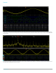
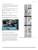
Datasheet Experience the performance difference Digital Phosphor technology with FastAcq™ highspeed waveform capture To debug a design problem, first you must know it exists. Digital phosphor technology with FastAcq provides you with fast insight into the real operation of your device. Its fast waveform capture rate - greater than 500,000 waveforms per second - gives you a high probability of seeing the infrequent problems common in digital systems: runt pulses, glitches, timing issues, and more.
4 Series MSO Multiple channel triggering. Visual Trigger areas can be associated with events spanning multiple channels, such as triggering on a specific burst-width on channel 1 and a specified bit pattern on channel 2. The wide variety of trigger types and context-sensitive help in the trigger menu make it easier than ever to isolate the event of interest.
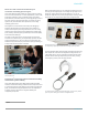
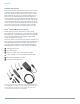
Datasheet TekVPI Probe Interface ® The TekVPI probe interface sets the standard for ease of use in probing. In addition to the secure, reliable connection that the interface provides, many TekVPI probes feature status indicators and controls, as well as a probe menu button right on the comp box itself. This button brings up a probe menu on the oscilloscope display with all relevant settings and controls for the probe.
4 Series MSO Comprehensive analysis for fast insight Basic waveform analysis Verifying that your prototype's performance matches simulations and meets the project's design goals requires careful analysis, ranging from simple checks of rise times and pulse widths to sophisticated power loss analysis, characterization of system clocks, and investigation of noise sources.
Datasheet Navigation and search Finding your event of interest in a long waveform record can be time consuming without the right search tools. With today's record lengths of many millions of data points, locating your event can mean scrolling through literally thousands of screens of signal activity. The 4 Series MSO offers the industry's most comprehensive search and ® waveform navigation with its innovative Wave Inspector controls. These controls speed panning and zooming through your record.
4 Series MSO Serial protocol triggering and analysis (optional) During debugging, it can be invaluable to trace the flow of activity through a system by observing the traffic on one or more serial buses. It could take many minutes to manually decode a single serial packet, much less the thousands of packets that may be present in a long acquisition.
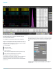
Datasheet Spectrum View (optional) Intuitive spectrum analyzer controls like center frequency, span and resolution bandwidth (RBW), independent from time domain controls, provide easy setup for frequency domain analysis. A spectrum view is available for each FlexChannel analog input, enabling multi-channel mixed domain analysis. It is often easier to debug an issue by viewing one or more signals in the frequency domain.
4 Series MSO Spectrum Time gates the range of time where the FFT is being calculated. Represented by a small graphical rectangle in the time domain view, it can be positioned to provide time correlation with the time domain waveform. Perfect for conducting Mixed Domain Analysis. Up to 11 automated peak markers provide frequency and magnitude values of each peak. The Reference marker is always the highest peak shown and is indicated in red. www.tek.
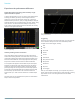
Datasheet Power analysis (optional) The 4 Series MSO has also integrated the optional 4-PWR-BAS/SUP4PWR-BAS power analysis package into the oscilloscope's automatic measurement system to enable quick and repeatable analysis of power quality, input capacitance, in-rush current, harmonics, switching loss, safe operating area (SOA), modulation, ripple, efficiency, amplitude and timing measurements, and slew rate (dv/dt and di/dt). The Power Analysis measurements display a variety of waveforms and plots.
4 Series MSO Designed with your needs in mind Connectivity The 4 Series MSO contains a number of ports which you can use to connect the instrument to a network, directly to a PC, or to other test equipment. Three USB 2.0 ports on the front and two more USB 2.0 host ports on the rear panel enable easy transfer of screen shots, instrument settings, and waveform data to a USB mass storage device. A USB mouse and keyboard can also be attached to USB host ports for instrument control and data entry.
Datasheet Help when you need it The 4 Series MSO includes several helpful resources so you can get your questions answered rapidly without having to find a manual or go to a website: Graphical images and explanatory text are used in numerous menus to provide quick feature overviews. All menus include a question mark icon in the upper right that takes you directly to the portion of the integrated help system that applies to that menu.
4 Series MSO Specifications All specifications are guaranteed unless noted otherwise. All specifications apply to all models unless noted otherwise. Model overview Oscilloscope MSO44 MSO46 4 6 4 6 Maximum digital channels (with optional logic probes) 32 48 Auxiliary Trigger Input ≤300 V RMS (Edge Trigger only) Bandwidth (calculated rise time) 200 MHz, 350 MHz, 500 MHz, 1 GHz, 1.5 GHz DC Gain Accuracy 50 Ω: ±1%, (±2.5% at 1 mV/Div and 500 µV/Div settings), de-rated at 0.
Datasheet Vertical system - analog channels Maximum input voltage 50 Ω: 5 VRMS, with peaks ≤ ±20 V (DF ≤ 6.25%) 1 MΩ: 300 VRMS For 1 MΩ, derate at 20 dB/decade from 4.5 MHz to 45 MHz; Derate at 14 dB/decade from 45 MHz to 450 MHz; > 450 MHz, 5.5 VRMS Effective bits (ENOB), typical High Res mode, 50 Ω, 10 MHz input with 90% full screen Bandwidth ENOB 1.5 GHz 7.1 1 GHz 7.6 500 MHz 7.9 350 MHz 8.2 250 MHz 8.2 20 MHz 8.9 Random noise, RMS, typical 1.
4 Series MSO Vertical system - digital channels Number of channels 8 digital inputs (D7-D0) per installed TLP058 (traded off for one analog channel) Vertical resolution 1 bit Minimum detectable pulse width, typical 1 ns Thresholds One threshold per digital channel Threshold range ±40 V Threshold resolution 10 mV Threshold accuracy ± [100 mV + 3% of threshold setting after calibration] Input hysteresis, typical 100 mV at the probe tip Input dynamic range, typical 30 Vpp for Fin ≤ 200 MHz, 10
Datasheet Horizontal system Delta-time measurement accuracy DTApp(typical) = 10 × DTARMS = ( ) ( ) ( ( )) N 2 N 2 + + 0.450 ps + 1 × 10-11 × tp 2 + TBA × tp SR1 SR2 ( ) ( ) ( ( )) N 2 N 2 + + 0.
4 Series MSO Trigger system Trigger level ranges Source Range Any Channel ±5 divs from center of screen Aux In Trigger, typical ±8 V Line Fixed at about 50% of line voltage This specification applies to logic and pulse thresholds. Trigger frequency counter 8-digits (free with product registration) Trigger types Edge: Positive, negative, or either slope on any channel. Coupling includes DC, AC, noise reject, HF reject, and LF reject Pulse Width: Trigger on width of positive or negative pulses.
Datasheet Trigger system Ethernet Bus (option 4SRENET): Trigger on Start of Frame, MAC Addresses, MAC Q-tag, MAC Length/Type, MAC Data, IP Header, TCP Header, TCP/IPV4 Data, End of Packet, and FCS (CRC) Error on 10BASE-T and 100BASE-TX buses Audio (I2S, LJ, RJ, TDM) Bus (option 4-SRAUDIO): Trigger on Word Select, Frame Sync, or Data. Maximum data rate for I2S/LJ/RJ is 12.5 Mb/s.
4 Series MSO Waveform measurements Amplitude measurements Amplitude, Maximum, Minimum, Peak-to-Peak, Positive Overshoot, Negative Overshoot, Mean, RMS, AC RMS, Top, Base, and Area Timing measurements Period, Frequency, Unit Interval, Data Rate, Positive Pulse Width, Negative Pulse Width, Skew, Delay, Rise Time, Fall Time, Phase, Rising Slew Rate, Falling Slew Rate, Burst Width, Positive Duty Cycle, Negative Duty Cycle, Time Outside Level, Setup Time, Hold Time, Duration N-Periods, High Time, and Low Time
Datasheet Spectrum View Center Frequency Limited by instrument analog bandwidth Span 18.6 Hz to 312.5 MHz Coarse adjustment in a 1-2-5 sequence Resolution Bandwidth (RBW) Window types and factors 93 μHz to 15.625 MHz Window type Factor Blackman-Harris 1.90 Flat-Top 2 3.77 Hamming 1.30 Hanning 1.44 Kaiser-Bessel 2.23 Rectangular 0.
4 Series MSO Display Color palettes Normal and inverted for screen captures Individual waveform colors are user-selectable Format YT, XY, and XYZ Local Language User Interface and Help English, Japanese, Simplified Chinese Arbitrary-Function Generator (optional) Function types Arbitrary, sine, square, pulse, ramp, triangle, DC level, Gaussian, Lorentz, exponential rise/fall, sin(x)/x, random noise, Haversine, Cardiac Sine waveform Frequency range 0.1 Hz to 50 MHz Frequency setting resolution 0.
Datasheet Arbitrary-Function Generator (optional) DC level range ±2.5 V into Hi-Z ±1.25 V into 50 Ω Random noise amplitude range 20 mVpp to 5 Vpp into Hi-Z 10 mVpp to 2.5 Vpp into 50 Ω Sin(x)/x Maximum frequency 2 MHz Gaussian pulse, Haversine, and Lorentz pulse Maximum frequency 5 MHz Lorentz pulse Frequency range 0.1 Hz to 5 MHz Amplitude range 20 mVpp to 2.4 Vpp into Hi-Z 10 mVpp to 1.2 Vpp into 50 Ω Cardiac Frequency range 0.
4 Series MSO Digital volt meter (DVM) Measurement types DC, ACRMS+DC, ACRMS Voltage resolution 4 digits Voltage accuracy DC: ±((1.5% * |reading - offset - position|) + (0.5% * |(offset - position)|) + (0.1 * Volts/div)) De-rated at 0.
Datasheet Input-Output ports Auxiliary output Rear-panel BNC connector. Output can be configured to provide a positive or negative pulse out when the oscilloscope triggers, the internal oscilloscope reference clock out, or an AFG sync pulse Characteristic Limits Vout (HI) ≥ 2.5 V open circuit; ≥ 1.0 V into a 50 Ω load to ground Vout (LO) ≤ 0.7 V into a load of ≤ 4 mA; ≤0.
4 Series MSO Environmental specifications Altitude Operating Up to 3,000 meters (9,843 feet) Non-operating Up to 12,000 meters (39,370 feet) Regulatory CE marked for the European Union and CSA approved for the USA and Canada RoHS compliant Software Software IVI driver Provides a standard instrument programming interface for common applications such as LabVIEW, LabWindows/CVI, Microsoft .NET, and MATLAB. Compatible with Python, C/C++/C# and many other languages through VISA.
Datasheet Ordering information Use the following steps to select the appropriate instrument and options for your measurement needs. Step 1 Start by selecting a model based on the number of FlexChannel inputs you need. Each FlexChannel input supports 1 analog or 8 digital input signals, interchangeably.
4 Series MSO Step 3 Add instrument functionality Instrument functionality can be ordered with the instrument or later as an upgrade kit. Instrument Option Built-in Functionality 4-RL-1 Extend record length from 31.25 Mpoints/channel to 62.5 Mpoints/channel 4-AFG Add Arbitrary / Function Generator 4-SEC 5 Add enhanced security for instrument declassification and password protected enabling and disabling of all USB and Ethernet ports and firmware upgrade.
Datasheet Step 7 Add analog probes and adapters Add additional recommended probes and adapters Recommended Probe / Adapter Description TAP1500 1.5 GHz TekVPI® active single-ended voltage probe, ±8 V input voltage TAP2500 2.
4 Series MSO Step 8 Add accessories Add traveling or mounting accessories Optional Accessory Description HC4 Hard carrying case with instrument front protective cover RM4 Rackmount kit SC4 Soft carrying case with instrument front protective cover Power Cord Option Description A0 North America power plug (115 V, 60 Hz) A1 Universal Euro power plug (220 V, 50 Hz) A2 United Kingdom power plug (240 V, 50 Hz) A3 Australia power plug (240 V, 50 Hz) A5 Switzerland power plug (220 V, 50 Hz) A6
Datasheet Feature upgrades after purchase Add feature upgrades in the future You can easily add functionality after the initial purchase. Node-locked licenses permanently enable optional features on a single product. Floating licenses allow license-enabled options to be easily moved between compatible instruments.
4 Series MSO Bandwidth upgrades after purchase Add bandwidth upgrades in the future You can easily upgrade the analog bandwidth of products after initial purchase. Bandwidth upgrades are purchased based on the number of FlexChannel inputs, the current bandwidth, and the desired bandwidth. All 4 Series MSO models can be upgraded in the field to any bandwidth.
Datasheet ASEAN / Australasia (65) 6356 3900 Belgium 00800 2255 4835* Central East Europe and the Baltics +41 52 675 3777 Finland +41 52 675 3777 Hong Kong 400 820 5835 Japan 81 (3) 6714 3086 Middle East, Asia, and North Africa +41 52 675 3777 People's Republic of China 400 820 5835 Republic of Korea +822 6917 5084, 822 6917 5080 Spain 00800 2255 4835* Taiwan 886 (2) 2656 6688 Austria 00800 2255 4835* Brazil +55 (11) 3759 7627 Central Europe & Greece +41 52 675 3777 France 00800 2255 4835* India 000 800 6