
Instructions


Operator Information
6
P6021 Instruction M anual
The P6021 is shielded to minimize the effect of external magnetic fields.
However, strong fields can interfere with the current signal being measured. If
you suspect that an external field is interfering with your measurement, remove
the probe from the conductor, but keep it in the same location as when you made
the suspect measurement. If a signal still appears on the oscilloscope, try to
measure the conductor current at a point farther from the location of the magnetic
field.
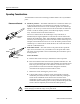
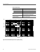
If you must measure current in the presence of a strong magnetic field, you can
minimize its interference by using two current probes and a differential-input
oscilloscope. To do so, follow these steps.
1. Connect the probes (with termination) to the positive and negative inputs of
the oscilloscope.
2. Clamp one probe around the conductor whose current you want to measure.
3. Place the other probe as close as possible to the first. Ensure that its slide
switch is completely closed, without a conductor inside it.
4. Set the oscilloscope to subtract the component of the signal that is common
to both probes.
5. Adjust the positions of the probes for best results. It may be difficult to
eliminate the undesirable signal completely, due to differences between the
probes or their terminations.
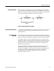
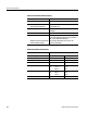
The flat-top response of any AC current probe displays a certain amount of
droop. This is caused by probe inductance loading the source impedance, causing
an L/R exponential decay. For short pulse widths, the response looks nearly flat.
The amount of droop can be calculated from the following relationship:
% Droop = 200 (π)Tf
wher e:
T=pulse duration in microseconds
f=lower 3 dB frequency of probe in Hertz
For example, to calculate the percent droop of a 100 s pulse measured with a
P6021 probe:
In the 10 mA/mV position, f=120 Hz
% Droop = 200 (π)Tf
= 200 (π) (100*10
--6
) (120)
= 0.075%
Probe Shielding
Droop