
User's Manual

Operating Basics
50 AFG3000 Series Quick Start User Manual
Trigger Out
The Trigger Output signal of the arbitrary/function generator is linked to run mode and function selected in CH1, if your
instrument is a dual-channel model.
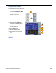
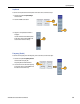
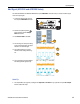
1. Connect the front-panel Trigge r
Output connector and the external
trigger input connector of the oscillo-
scopes. The Trigger Output connector
provides the trigger signal for oscillo-
scopes.
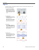
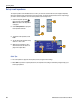
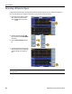
2. Continuous mode:
The trigger output is a square wave-
form and the rising edge at the start of
each waveform period.
When an output frequency is higher
than 4.9 MHz, some restrictions are
applied. See the Quick Tips below.
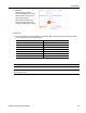
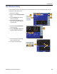
3. Sweep mode:
When the Repeat or Trigg er sweep
mode and internal trigger source are
selected, the trigger output is a square
waveform and the rising edge at the
start of each sweep.
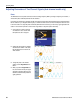
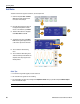
4. Modulation mode:
When internal modulation source is
selected, the trigger output is a square
waveform of the same frequency as
the modulating signal.
When an external modulation source is
selected, the trigger output is disabled.
1
2
3
4