Service Manual AWG510 & AWG520 Arbitrary Waveform Generator 071-0101-50 Warning The servicing instructions are for use by qualified personnel only. To avoid personal injury, do not perform any servicing unless you are qualified to do so. Refer to all safety summaries prior to performing service. www.tektronix.
Copyright Tektronix Japan, Ltd. All rights reserved. Copyright Tektronix, Inc. All rights reserved. Tektronix products are covered by U.S. and foreign patents, issued and pending. Information in this publication supercedes that in all previously published material. Specifications and price change privileges reserved. Tektronix Japan, Ltd., 5–9–31 Kitashinagawa, Shinagawa–ku, Tokyo 141–0001 Japan Tektronix, Inc., P.O.
Tektronix warrants that the products that it manufactures and sells will be free from defects in materials and workmanship for a period of one (1) year from the date of shipment. If a product proves defective during this warranty period, Tektronix, at its option, either will repair the defective product without charge for parts and labor, or will provide a replacement in exchange for the defective product.
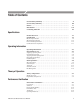
Table of Contents General Safety Summary . . . . . . . . . . . . . . . . . . . . . . . . . . . . . . . . . . . . Service Safety Summary . . . . . . . . . . . . . . . . . . . . . . . . . . . . . . . . . . . . . Preface . . . . . . . . . . . . . . . . . . . . . . . . . . . . . . . . . . . . . . . . . . . . . . . . . . . Introduction . . . . . . . . . . . . . . . . . . . . . . . . . . . . . . . . . . . . . . . . . . . . . . . Contacting Tektronix . . . . . . . . . . . . . . . . . . . . . . . . . . . . . . . .
Table of Contents Clock Frequency Tests . . . . . . . . . . . . . . . . . . . . . . . . . . . . . . . . . . . . . . . . . . . . . Amplitude and Offset Accuracy Tests (Normal Out) . . . . . . . . . . . . . . . . . . . . . Amplitude, Offset Accuracy and Rise Time Tests (Direct DA Out) . . . . . . . . . . Pulse Response Tests . . . . . . . . . . . . . . . . . . . . . . . . . . . . . . . . . . . . . . . . . . . . . . Sine Wave Tests . . . . . . . . . . . . . . . . . . . . . . . . . . . . . . . . . . . . . . .
Table of Contents Diagrams Diagrams . . . . . . . . . . . . . . . . . . . . . . . . . . . . . . . . . . . . . . . . . . . . . . . . . 9–1 Replaceable Mechanical Parts . . . . . . . . . . . . . . . . . . . . . . . . . . . . . . . . 10–1 Parts Ordering Information . . . . . . . . . . . . . . . . . . . . . . . . . . . . . . . . . . . . . . . . . Using the Replaceable Parts List . . . . . . . . . . . . . . . . . . . . . . . . . . . . . . . . . . . . .
Table of Contents List of Figures Figure 1–1: Dimensions . . . . . . . . . . . . . . . . . . . . . . . . . . . . . . . . . . . . . . Figure 1–2: Signal timing . . . . . . . . . . . . . . . . . . . . . . . . . . . . . . . . . . . . 1–15 1–19 Figure 2–1: Menu buttons, bezel menu buttons, and the CLEAR MENU button . . . . . . . . . . . . . . . . . . . . . . . . . . . . . . . . . . . . . . . . . . . . . . . . . 2–9 Figure 2–2: Bottom and side menus . . . . . . . . . . . . . . . . . . . . . . . . . . .
Table of Contents Figure 4–20: Trigger Signal (–5V check2) . . . . . . . . . . . . . . . . . . . . . . . Figure 4–21: Event input and enhanced mode initial test hookup . . . Figure 4–22: Waveform while all ground disclosure switches are open ....................................................... Figure 4–23: Waveform output when the SW1 is closed . . . . . . . . . . . Figure 4–24: Waveform output when the SW2 is closed . . . . . . . . . . . Figure 4–25: Waveform output when the SW3 is closed . . . . . . .
Table of Contents Figure 6–7: Cabinet removal . . . . . . . . . . . . . . . . . . . . . . . . . . . . . . . . . Figure 6–8: Trim ring, Menu buttons, and Output panel removal . . . . . . . . . . . . . . . . . . . . . . . . . . . . . . . . . . . . . . . . . . . . . . . . Figure 6–9: A20 Front-Panel Assembly removal . . . . . . . . . . . . . . . . . Figure 6–10: Disassembly of Front-Panel Assembly . . . . . . . . . . . . . . Figure 6–11: Cabinet modules removal . . . . . . . . . . . . . . . . . . . . . . . .
Table of Contents Figure 10–1: Cabinet . . . . . . . . . . . . . . . . . . . . . . . . . . . . . . . . . . . . . . . . Figure 10–2: Front panel . . . . . . . . . . . . . . . . . . . . . . . . . . . . . . . . . . . . Figure 10–3: Outer chassis modules . . . . . . . . . . . . . . . . . . . . . . . . . . . Figure 10–4: Circuit boards . . . . . . . . . . . . . . . . . . . . . . . . . . . . . . . . . . Figure 10–5: CPU unit . . . . . . . . . . . . . . . . . . . . . . . . . . . . . . . . . . . . . .
Table of Contents List of Tables viii Table 1–1: AWG 500-Series waveform editors . . . . . . . . . . . . . . . . . . Table 1–2: Operation modes . . . . . . . . . . . . . . . . . . . . . . . . . . . . . . . . . Table 1–3: Arbitrary waveforms . . . . . . . . . . . . . . . . . . . . . . . . . . . . . Table 1–4: Clock generator . . . . . . . . . . . . . . . . . . . . . . . . . . . . . . . . . Table 1–5: Internal trigger generator . . . . . . . . . . . . . . . . . . . . . . . . . Table 1–6: Main output . . .
Table of Contents Table 4–4: Performance test items . . . . . . . . . . . . . . . . . . . . . . . . . . . . Table 4–5: Test equipments . . . . . . . . . . . . . . . . . . . . . . . . . . . . . . . . . . Table 4–6: Waveforms and sequences in performance check disk . . 4–12 4–13 4–16 Table 5–1: Adjustments . . . . . . . . . . . . . . . . . . . . . . . . . . . . . . . . . . . . . Table 5–2: Test equipment . . . . . . . . . . . . . . . . . . . . . . . . . . . . . . . . . . .
Table of Contents AWG510 & AWG520 Service Manual
General Safety Summary Review the following safety precautions to avoid injury and prevent damage to this product or any products connected to it. To avoid potential hazards, use this product only as specified. Only qualified personnel should perform service procedures. To Avoid Fire or Personal Injury Use Proper Power Cord. Use only the power cord specified for this product and certified for the country of use. Connect and Disconnect Properly.
General Safety Summary Symbols and Terms Terms in this Manual. These terms may appear in this manual: Warning statements identify conditions or practices that could result in injury or loss of life. Caution statements identify conditions or practices that could result in damage to this product or other property. Terms on the Product. These terms may appear on the product: DANGER indicates an injury hazard immediately accessible as you read the marking.
Service Safety Summary Only qualified personnel should perform service procedures. Read this Service Safety Summary and the General Safety Summary before performing any service procedures. Do Not Service Alone. Do not perform internal service or adjustments of this product unless another person capable of rendering first aid and resuscitation is present. Disconnect Power. To avoid electric shock, disconnect the mains power by means of the power cord or, if provided, the power switch.
Service Safety Summary AWG510 & AWG520 Service Manual
Preface This is the service manual for the AWG510 and AWG520 Arbitrary WaveformGenerator. The manual contains information needed to service the waveform generator to the module level. Manual Structure This manual is divided into sections, such as Specifications and Theory of Operation. Further, some sections are divided into subsections, such as Product Description and Removal and Installation Procedures. Sections containing procedures also contain introductions to those procedures.
Preface Manual Conventions This manual uses certain conventions that you should become familiar with. Some sections of the manual contain procedures for you to perform. To keep those instructions clear and consistent, this manual uses the following conventions: Modules Safety Names of front panel controls and menus appear in the same case (initial capitals, all uppercase, etc.) in the manual as is used on the waveform generator front panel and menus.
Introduction This manual contains information needed to properly service the AWG510 and AWG520 Arbitrary Waveform Generators, as well as general information critical to safe and effective servicing.
Introduction Tektronix Service Offerings Tektronix provides service to cover repair under warranty as well as other services that may provide a cost-effective answer to your service needs. Whether providing warranty repair service or any of the other services listed below, Tektronix service technicians are well equipped to service the waveform generator.
Introduction Contacting Tektronix Phone 1-800-833-9200* Address Tektronix, Inc. Department or name (if known) 14200 SW Karl Braun Drive P.O. Box 500 Beaverton, OR 97077 USA Web site www.tektronix.com Sales support 1-800-833-9200, select option 1* Service support 1-800-833-9200, select option 2* Technical support Email: techsupport@tektronix.com 1-800-833-9200, select option 3* 1-503-627-2400 6:00 a.m. – 5:00 p.m. Pacific time * This phone number is toll free in North America.
Introduction AWG510 & AWG520 Service Manual
Product Overview The AWG510 and AWG520 Arbitrary Waveform Generators can generate both simple and arbitrary waveforms. The AWG510 generates one-channel differential output, while the AWG520 generates two-channel single-end arbitrary waveforms and function generator waveforms. The AWG500-Series Generator contains a 1 GHz clock frequency, a 10-bit DA converter, and a 4 M-word waveform memory.
Product Overview AWG510 & AWG520 Service Manual
Specifications This section contains the AWG510 and AWG520 Arbitrary Waveform Generator specifications. All specifications are guaranteed unless labeled “typical”. Typical specifications are provided for your convenience but are not guaranteed.
Specifications Electrical Specification Table 1-2: Operation modes Characteristics Description Continuous Waveform is continuously output in this mode. When a sequence is defined, waveforms are sequentially or repeatedly output in the order defined by the sequence. The extended sequence functions such as trigger input, event jump, etc. are neglected in this mode. Triggered Waveform is output only once when a trigger event is created.
Specifications Table 1-4: Clock generator Characteristics Description Sampling frequency 50.000 000 kHz to 1.000 000 0 GHz Resolution 8 digits PV reference page Internal clock 1 1 * Frequency accuracy "1 ppm (25 _C), during 1 year after calibration Phase noise, Typical -80 dBc / Hz (1 GHz with 10 kHz offset) -100 dBc/Hz (1 GHz with 100 kHz offset) Page 4-30 The internal reference oscillator is used.
Specifications Table 1-6: Main output (Cont.) Characteristics 3 Description PV reference page Normal out Output voltage -2.0 V to +2.0V, into a 50 W load Amplitude Range 20 mVp-p to 2 Vp-p, into a 50 W load Resolution 1 mV * DC accuracy "(1.5 % of amplitude + 2 mV), offset: 0 V Page 4-32 Offset Range -1.000 V to 1.000 V, into a 50 W load Resolution 1 mV * Offset accuracy "(1 % of offset + 10 mV), 20 mV amplitude (waveform data: 0) Reverse power protection Up to 0.
Specifications Table 1-6: Main output (Cont.) Characteristics 3 Description PV reference page Direct DA out Output voltage 0.5 VpĆp (with -0.27 V offset), into a 50 W load * DC accuracy Amplitude 0.5 VpĆp "10 % DC offset -0.27 V "10 % * Pulse response 3 (Waveform data: -1 and 1) Rise time (10 % to 90 %) x 700 ps Fall time (10 % to 90 %) x 700 ps Page 4-36 Page 4-40 The characteristics are specified at the end of the BNC cable (012Ć0482Ć00).
Specifications Table 1-8: Auxiliary outputs Characteristics Description PV reference page Marker 4 Number of markers AWG510 2 AWG520 4 ( Note that the markers are not additionally installed even when the Option 03 is installed. ) Level (Hi/Lo) -2.0 V to +2.0 V, into a 50 W load -4.0 V to +4.0 V, into a 1 MW load Resolution 0.05 V * Accuracy Within "(0.1 V +5 % of setting) Rise and fall times (10 % to 90 %), Typical 0.5 ns (1 VpĆp, Hi: +0.5 V, Lo: -0.5 V) 1.0 ns (2 VpĆp,Hi: +1 V, Lo: -1 V) 2.
Specifications Table 1-8: Auxiliary outputs (Cont.) Characteristics Description PV reference page Noise 5 Level -145 dBm / Hz to -105 dBm / Hz Attenuator 1 dB step Accuracy "2.5 dB (at 100 MHz, -105 dBm/Hz) Connector Rear panel BNC connectors Type Gaussian Page 4-78 4 The characteristics are specified at the end of the SMB-BNC cable (012Ć1459Ć00). 5 The characteristics are specified at the end of the BNC cable (012Ć0482Ć00).
Specifications Table 1-11: Period JItter (CLOCK OUT) Clock 1 GS/s 800 MS/s 400 MS/s Measurement StdDev Pk-Pk StdDev Pk-Pk StdDev Pk-Pk AWG520 11.0 ps 42.0 ps 11.0 ps 42.0 ps 11.0 ps 42.0 ps AWG520 OP3 14.0 ps 50.0 ps 14.0 ps 50.0 ps 14.0 ps 50.0 ps AWG510 5.5 ps 30.0 ps 5.5 ps 30.0 ps 5.5 ps 30.0 ps AWG510 OP3 11.0 ps 75.0 ps 11.0 ps 50.0 ps 11.0 ps 50.
Specifications Table 1-13: Digital data out (option 03) (Cont.) Characteristics 6 Description PV reference page Delay 6 Data to marker 4.4 ns See Figure 1-2 for Td5. Clock to data 3.7 ns See Figure 1-2 for Td6. The characteristics are specified at the end of the SMB-BNC cable (012Ć1459Ć00).
Specifications Table 1-14: Auxiliary inputs (Cont.) Characteristics Description Threshold TTL level Pulse width Minimum 64 clocks Input voltage range 0 V to +5 V (DC + peak AC) Impedance 2.2 kW, pullĆup to +5 V Delay to analog out x 462.
Specifications Table 1-15: Funcion GeneratorĂ(FG) Characteristics Description Operation Mode Continuous mode only Waveform Shape Sine, Triangle, Square, Ramp, Pulse, DC Frequency 1.000 Hz to 100.0 MHz Amplitude Range 0.020 VpĆp to 2.000 VpĆp, into a 50 W load Resolution 1 mV Offset Range -1.000 V to +1.000 V, into a 50 W load Resolution 1 mV DC Level DC waveform only Range -1.000 V to +1.
Specifications Table 1-16: Display Characteristics Description Display Display area Resolution Horizontal 13.2 cm (5.2 inches) Vertical: 9.9 cm (3.9 inches) 640 (H) 480 (V) pixels Table 1-17: Timer Characteristics Description Timer Operation life 6 years Type Li 3 V, 190 mAh Table 1-18: AC line power Characteristics Description Rating voltage 100 to 240 VAC Voltage Range 90 to 250 VAC, continuous range, CAT II Source frequency 48.
Specifications Mechanical Specification Table 1-20: Mechanical Characteristics Description Net weight 17 kg (37.5 lb) (AWG520) Dimensions Height 178 mm (7.0 inches) 194 mm (7.64 inches) with Feet Width 422 mm (16.6 inches) 434 mm (17.1 inches) with Handle Length 560 mm (22.0 inches) 602 mm (23.
Specifications Environmental Specification Table 1-21: Installation requirement Characteristics Description Heat dissipation Maximum power 600 W (maximum line current: 8 Arms, at 50 Hz) Surge Current 30 A (25 _C) peak for equal to or less than 5 line cycles, after the instrument has been turned off for at least 30s Cooling clearance Bottom 2 cm (0.8 inches) Sides 15 cm (6 inches) Rear 7.
Specifications Certification and Compliances The certification and compliances for the AWG510 and AWG520 Arbitrary Waveform Generator are listed in Table 1–23. Table 1-23: Certifications and compliances EC declaration of conformity EMC Meets intent of Directive 89/336/EEC for Electromagnetic Compatibility.
Specifications Table 1-23: Certifications and compliances (Cont.) Installation category Description Pollution degree Terminals on this product may have different installation (over-voltage) category designations. The installation categories are: CAT III DistributionĆlevel mains (usually permanently connected). Equipment at this level is typically in a fixed industrial location CAT II LocalĆlevel mains (wall sockets).
Specifications Ext. Trigger Clock to analog (10.6 ns [typ]) Td1 (37 ns [tpy] + 1 clk) Analog Out Td2 (30 ns [tpy] + 1 clk) Marker (Marker skew 32 ps [typ]) Td5 (4.4 ns [typ]) Digital Out (D.O skew 330 ps [typ]) Td7 Td6 (3.7 ns [typ]) (Trigger to clock: 20 ns + 1.
Specifications AWG510 & AWG520 Service Manual
Operating Information This section is divided into following two subsections: Preparation for Use. Describes the installation, environmental requirements, information on how to power on or off, and so on. Instruction for Operation. Describes the general menu operating information and Diag/Cal menu structure.
Operating Information AWG510 & AWG520 Service Manual
Preparation for Use This subsection describes: Supplying Operating Power Operating Environment Applying and Interrupting Power. Supplying Operating Power . Read all information and heed all warnings in this subsection before connecting the AWG500 to a power source. AC POWER SOURCE AND CONNECTION. The waveform generator operates from a single-phase power source. It has a three-wire power cord and two-pole, three-terminal grounding type plug.
Preparation for Use Power Cord Information A power cord with the appropriate plug configuration is supplied with each AWG500. Table 2–1 gives the color-coding of the conductors in the power cord. If you require a power cord other than the one supplied, refer to Table 2–2, Power Cord Identification.
Preparation for Use Operating Voltage This AWG500 operates with any line voltage from 100 to 240 VACRMS with any line frequency from 48 to 63 Hz. There are two fuses, either of which may be used throughout the line voltage and frequency ranges. (The two fuses are not interchangeable as each requires a different fuse cap.) Memory Backup Power Memory modules with on-board batteries allow the AWG500 to retain some types of data upon loss of the AC power source.
Preparation for Use Operating Environment The following environmental requirements are provided to ensure proper operation and long instrument life. Operating Temperature Operate the waveform generator where the ambient air temperature is from 10_ C to +40_ C with no diskette in the floppy drive. Store the AWG500 in ambient temperatures from –20_ C to +60_ C with no diskette in the floppy drive.
Preparation for Use Applying and Interrupting Power Consider the following information when you power on or power off the instrument, or when power is interrupted due to an external power failure. You can not power on the instrument when the ambient temperature exceeds the instrument temperature operation range. Wait until the instrument cools down, or the ambient temperature decreases to valid operating temperatures, before turning on the instrument again.
Preparation for Use Repackaging Instructions Use a corrugated cardboard shipping carton having a test strength of at least 375 pounds and with an inside dimension at least six inches greater than the instrument dimensions. If the instrument is being shipped to a Tektronix Service Center, enclose the following information: the owner’s name, address, phone number of a contact person, type and serial number of the instrument, reason for returning, and a complete description of the service required.
Basic Operations This section describes the AWG500-Series Waveform Generator menu system and numeric and text input methods. Menu Operations There are four menu buttons, labeled EDIT, SETUP, APPL, and UTILITY, as shown in Figure 2–1. Pushing a menu button displays the corresponding screen and menu buttons. These menus let you edit waveforms, initialize instrument settings, define instrument operation, and specify waveform output parameters.
Operating Information Menu Elements Pushing a front-panel menu button displays that buttons screen and bottom menu items. You select a bottom menu item by pushing the button directly below that menu item. Pushing a bottom button displays a side menu, pop-up menu, list, or dialog box. Figures 2–2 through 2–4 show examples of the side menu, pop-up menu and dialog box, respectively.
Operating Information Table 2-3: Side menu elements Menu items Descriptions Menu items Descriptions ! " ! ! " ! ! "
Operating Information A dialog box, shown in Figure 2–4, displays a form in which you make selections or enter values. Use the front-panel arrow buttons to move in the list and select items or fields. Use the keypad buttons or the general purpose knob to change values in selected text/numeric fields or change 1-of-N fields. Push the OK side button to confirm the dialog box; push the Cancel side button or the CLEAR MENU button to exit the dialog box without making any changes.
Operating Information Numeric Input You can enter numeric values by using either the numeric keypad or the general purpose knob. If the side menu item displays a value, you can alter this value using the general purpose knob or numeric buttons. Pushing the type of side menu button or selecting a parameter in a pop-up menu causes the current setting to appear on the right end of the Status Display area as shown in Figure 2–5.
Operating Information The Numeric Keypad Figure 2–6 shows the numeric keypad, with descriptions of the button operations.
Operating Information Note that the current unit is always kept when you just use the ENTER after entering digits. For example, suppose that the Clock is currently set to 100.0 MS/s. When you press 5, 0 and ENTER buttons in this order, the Clock will be set to 50.0 MS/s. To set to 500 kS/s, press 0, ., 5 and ENTER buttons, or 5, 0, 0, SHIFT, and 8 buttons in this order.
Operating Information To select a character from the character palette, use the general purpose knob to highlight a character and then push the ENTER to insert the character into the text field at the location of the character underscore. Repeat this step until you have entered all characters in the text field. By default, the character palette is selected. To select text from a file name list, use the y and b arrow buttons to move the knob icon to the file name list.
Operating Information Shortcut Controls Figure 2–8 shows the shortcut buttons and knobs that control specific instrument setup parameters. Using the shortcut controls lets you adjust the output setup parameters even while you are displaying another menu. Table 2–5 describes the shortcut controls.
Operating Information Table 2-5: Shortcut control descriptions (cont.) Controls Descriptions Adjusts the clock setting. This is the same as selecting SETUP (front) Horizontal (bottom) Clock (side), and then turning the general purpose knob. TRIGGER Displays the Trigger side menu. This is the same as selecting SETUP (front) Trigger (bottom). Adjusts the trigger level setting. This is the same as selecting SETUP (front) Trigger (bottom) Level (side), and then turning the general purpose knob.
Operating Information and Directory bottom menu buttons to open side menus that let you change the current drive location. Table 2–7 describes the Drive and Directory bottom buttons.
Operating Information Renaming Files Renaming files is done from the EDIT menu screen. Do the following steps to rename a file: 1. Push EDIT (front). The instrument displays the file list. 2. Select the file to rename. 3. Push File (bottom) Rename (side) 4. Enter the new name for the file in the file name field 5. Push OK (side). The file is renamed. Deleting Files Deleting files is done from the EDIT menu screen. Do the following steps to delete a file: 1. Push EDIT (front).
Operating Information Figure 2-9: Files and directories with read only attribute Saving Files File saving is done from within each editor screen. You have the choice of saving your waveform data to the current file name or to a new file name. To save a waveform to its current file name, push File (bottom) Save (pop-up) OK (side).
Operating Information . When you exit an editor without saving edited data, the instrument displays the message Save the changes you made?. Push the Yes side button to save the waveform data. To save waveform data to a new file name, push File (bottom) Save As (pop-up) OK (side). The instrument opens the Input Filename dialog box, shown in Figure 2–10. Use this dialog box to enter a file name. If necessary, you can select a storage media or directory by pushing the Drive... side menu button.
Theory of Operation This section describes the electrical operation of the AWG510 and AWG520 Arbitrary Waveform Generator of the major circuit blocks or modules. Refer to Figure 9–1 while reading this text. Module Overview The AWG510 and AWG520 are portable dual–channel waveform generator (differential for the AWG510 and single–ended for the AWG520). The waveform generator reads the digital waveform data loaded into its waveform memory. The point rate clock determines the rate at which the data is read.
Theory of Operation Analog Processing (A71/A72, Analog Output Board) This functional block amplifies the DAC analog signals to the specified output level. The input signals may pass through the low–pass filters and attenuators in this block. If an offset is specified, the Offset circuitry will add it. This board also has an adder circuitry for adding the signal from the A75 Noise Generator board or the Add Input on the rear panel to the output waveform.
Theory of Operation A30, GPIB Board. The fourth slot of the CPU Unit has the General Purpose Interface Bus (GPIB) interface driver, which controls communication with external devices over the parallel interface. The GPIB connector is on the rear panel. The GPIB Board also has the bus that sends the control signals to the Clock, AWG, and Analog Output board.
Theory of Operation Digital Data Out Option 03 The Digital Data Out option (03) directly outputs the digital data in the waveform memory without passing it through the digital-to-analog converter. This option is installed on the AWG board. For more information about options, refer to section 7, Option.
Performance Verification Two types of Performance Verification procedures can be performed on this product: SelfTests and Performance Tests. You may not need to perform all of these procedures, depending on what you want to accomplish. To rapidly confirm that the Waveform Generator functions and was adjusted properly, just do the Self Tests, which begin on page 4–3.
Performance Verification Each procedure consists of as many steps, substeps, and subparts as required to do the test. Steps, substeps, and subparts are sequenced as follows: 1. First Step a. First Substep First Subpart Second Subpart b. Second Substep 2. Second Step Instructions for menu selection on follow this format: FRONT PANEL BUTTON Main Menu Button Side Menu Button.
Performance Verification Self Tests The Self Tests use internal routines to confirm basic functionality and proper adjustment. No test equipment is required to do these test procedures. The self tests include these internal routines: Diagnostics This self-test procedure uses internal routines to verify that the instrument functions, and passes the internal circuit tests. Calibration The second procedure checks the instrument internal calibration constants and changes them if needed.
Performance Verification The list on the screen shows the test items and results in the calibration and diagnostics previously made. For the diagnostics, in addition to selecting all of the test items shown on the screen, you can select only a test item that you want to run using the general purpose knob. The result of the diagnostics are shown as error code. Pass means that the tests have been made without error. If an error is detected, error code is displayed.
Performance Verification See Table 4–1 for details on error codes. 3. Return to regular service: Push any bottom or menu button (other than UTILITY) to exit the diagnostic screen. Calibration The instrument includes internal calibration routines that check electrical characteristics such as offset, attenuations and filters. Perform calibration to adjust internal calibration constants as necessary. This procedure describes how to do the internal calibration.
Performance Verification Figure 4-2: Calibration result message box c. Confirm that no failures are found: Verify that no failures are found and reported in the message box. If the calibration displays Fail as the result, consult a qualified service technician for further assistance. 3. Return to regular service: Push the OK side button and then any bottom or menu button (other than the UTILITY) to exit the diag screen. .
Performance Verification Table 4-1: Diagnostic categories and error codes Categories Error codes Descriptions System 2100 2101 2102 2103 2104 2105 2106 Bios test error Realtime clock power fail CMOS checksum fail FDD missing fail Memory size fail Flash disk fail Date and time fail 2110 Front panel test error Configuration fail Communication fail RAM fail ROM fail AD fail Timer fail Run mode Clock AWG510 & AWG520 Service Manual 2111 2112 2113 2114 2115 2116 2300 2301 A30 board test error Unreco
Performance Verification Table 4-1: Diagnostic categories and error codes (Cont.
Performance Verification Table 4-1: Diagnostic categories and error codes (Cont.
Performance Verification Finding Faulty Modules Table 4–2 shows the module test error code examples. The error code composes of 54XX and 57XX, which corresponds to J7XX and J6XX modules and to J12XX and J11XX, respectively. The lower two digits (XX) indicates the possible faulty module, whose lower 6 bits correspond to the modules as shown in Table 4–2. The 1 in the table indicates a possible faulty module. For example, the 1s are placed in the J620 and J610 columns for the line of the error code 5406.
Performance Verification Table 4-3: Waveform memory cell test errors Faulty modules Faulty memory cellll J600 J610 J620 J700 J710 J720 J1100 J1110 J1120 J1200 J1210 J1220 U100 01 09 17 25 33 41 U110 02 10 18 26 34 42 U120 03 11 19 27 35 43 U130 04 12 20 28 36 44 U140 05 13 21 29 37 45 U150 06 14 22 30 38 46 U160 07 15 23 31 39 47 U170 08 16 24 32 40 48 AWG510 & AWG520 Service Manual 4-11
Performance Verification Performance Tests This section contains a collection of procedures for checking that the AWG500–Series Waveform Generator performance as warranted.
Performance Verification . These procedures extend the confidence level provided by the basic procedures described on page 4–3. The basic procedures should be done first, then these procedures performed if desired. Prerequisites Related Information Equipment Required The tests in this section comprise an extensive, valid confirmation of performance and functionality when the following requirements are met: H The cabinet must be installed on the instrument.
Performance Verification Table 4-5: Test equipments (cont.) Item number and description Minimum requirements Example (recommended) Purpose 50 W, male SMB to male BNC connectors Tektronix part number 012Ć1459Ć00 Signal interconnection 10. BNC to N Connector Male BNC to female N Tektronix part number 103Ć0045Ć00 Signal interconnection 11. BNCĆT Connector Mail BNC to female BNC to female BNC Tektronix part number 103Ć0030Ć00 Signal interconnection 12.
Performance Verification Loading Files The following steps explain how to load files from the Performance Check/Adjustment disk (063-2983-XX) into waveform memory and/or sequence memory. 1. Insert the disk into the Waveform Generator floppy disk drive. 2. Select SETUP (front) Waveform/Sequence (bottom) Load... (side) Drive... (side) to display the Select Drive dialog box. The dialog box is as show in Figure 4–4. 3.
Performance Verification . The floppy disk file list displayed on the screen does not automatically update when you replace the diskette with another one. To update the file list, re-select the floppy disk drive.
Performance Verification Table 4-6: Waveforms and sequences in performance check disk (Cont.) No. File name EDIT menu Form SETUP menu Marker setup Points Clock Filter Ampl Offset 100 1 MHz Through 1ĂV 0ĂV Usage 11 TRIG.WFM Trigger input 12 PT_EVENT.SEQ Event input 13 PT_STROB.SEQ Event input 14 S260.WFM (PT_xxxxx.SEQ) 2 260 100 MHz Through 1ĂV 0ĂV Event input 15 S260H.WFM (PT_xxxxx.SEQ) 2 260 100 MHz Through 1ĂV 0ĂV Event input 16 R260H.WFM (PT_xxxxx.
Performance Tests Test Record Photocopy the following 4 pages and use them to record the performance test results for your AWG510/520.
Performance Tests AWG510 & AWG520 Test Record (Page 1 of 4) Serial Number: Certificate Number: Calibration Date: Technician: Clock frequency tests Low limit 10 MHz clock frequency accuracy 9,999,990 Hz Amplitude and offset tests Low limit CH1 Amplit de accuracy Amplitude acc rac 20 mV 17.7 mV 22.3 mV 200 mV 195 mV 205 mV 2V 1.968 V 2.032 V 20 mV 17.7 mV 22.3 mV 200 mV 195 mV 205 mV 2V 1.968 V 2.032 V 0V -10 mV +10 mV 1V 0.980 V 1.020 V -1 V -1.020 V -0.
Performance Tests AWG510 & AWG520 Test Record (Page 2 of 4) Pulse response tests CH1 1 V amplitude amplit de CH1 2 V amplitude amplit de CH2 or CH1 1 V amplitude amplit de CH2 or CH1 2 V amplitude amplit de Low limit Test result Rise time High limit 1.5 ns Aberration -7 % +7 % Flatness (after 50 ns) -3 % +3 % Rise time 2.5 ns Aberration -10 % +10 % Flatness (after 50 ns) -3 % +3 % Rise time 1.5 ns Aberration -7% +7 % Flatness (after 50 ns) -3 % +3 % Rise time 2.
Performance Tests AWG510 & AWG520 Test Record (Page 3 of 4) Add input tests $#!$# % Low limit " " " " " " " " High limit !$# !$# Marker output tests Test result Low limit Test result High limit & % % & % % & % % & % % Di
Performance Tests AWG510 & AWG520 Test Record (Page 4 of 4) Digital data output tests (Option 03 only) Low limit $#!$# % & % % & % % $#!$# % Test result ' $ " & #& " Noise output tests Low limit " % # ( ( ( 4-22 High limit Test result High limit ( AWG510 & AWG520 Service Manual
Performance Verification Operating Mode Tests These procedures check operation of the Cont, Triggered and Gated modes. Check Cont Mode Equipment required A 50ĂΩ coaxial cable and an oscilloscope. Prerequisites The AWG500-Series Waveform Generator must meet the prerequisites listed on page 4-13. 1. Install the test hookup and set test equipment controls: a.
Performance Verification 2. Set the AWG500–Series Waveform Generator controls and select the waveform file: a. Initialize the AWG500–Series Waveform Generator controls: Push UTILITY (front–panel) System (bottom) Factory Reset (side) OK (side). b. Select the waveform file: Load the MODE.WFM as referring to the procedures on page 4–15. 3. Turn on the AWG500–Series Waveform Generator CH1 output: Push the RUN and CH1 OUT buttons so that the LEDs above the RUN button and CH1 output connector light. 4.
Performance Verification AWG500 Series Waveform Generator rear panel Function Generator (AFG310) BNC T Adapter Connect the cable to the TRIG IN connector through the BNC T adapter. Oscilloscope Connect the cable to the CH1 output connector on the front-panel Connect the cable to the TRIG IN connector through the BNC T adapter. Figure 4-6: Triggered mode initial test hookup c. Set the oscilloscope controls: Vertical . . . . . . . . . . . . . . . . . . . . . . . . . CH1 coupling . . . . . . . . . . . .
Performance Verification 2. Set AWG500–Series Waveform Generator controls and select the waveform file: a. Initialize the AWG500–Series Waveform Generator controls: Push UTILITY (front–panel) System (bottom) Factory Reset (side) OK (side). b. Set triggered mode: Push SETUP (front–panel) Run Mode (bottom) Triggered (side) to set the AWG500–Series Waveform Generator to triggered mode. c. Select the file: Load the MODE.WFM as referring to the procedures on page 4–15. 3.
Performance Verification 6. End procedure: Turn off the function generator output. Retain the test hookup. Check Gated Mode Equipment required Three 50ĂΩ coaxial cables, an adapter (BNC T male to 2 females), a function generator, and an oscilloscope. Prerequisites The AWG500-Series Waveform Generator meets the prerequisites listed on page 4-13. 1. Use the test hookup from previous check. 2. Set the test equipment controls: a. Set the oscilloscope controls: Vertical . . . . . . . . . . . . . . . . . .
Performance Verification a. Initialize the AWG500–Series Waveform Generator controls: Push UTILITY (front–panel) System (bottom) Factory Reset (side) OK (side). b. Set gated mode: Push SETUP (front–panel) Run Mode (bottom) Gated (side). c. Select the waveform file: Load the MODE.WFM as referring to the procedures on page 4–15. 4. Turn on the AWG500–Series Waveform Generator CH1 output: Push the RUN and CH1 OUT buttons so that the LEDs above the RUN button and CH1 output connector light. 5.
Performance Verification e. Change the AWG500–Series Waveform Generator trigger polarity to negative: Push SETUP (front–panel) Trigger (bottom) Negative (side). f. Check gated mode with a negative gate signal: Check that the oscilloscope displays a sine wave while the function generator gate signal amplitude is equal to or less than 1 V. 7. End procedure: Turn off the function generator output, and disconnect the function generator and oscilloscope.
Performance Verification Clock Frequency Tests These procedures check the AWG500–Series Waveform Generator clock frequency accuracy. Equipment required A 50ĂΩ coaxial cable, a 50ĂΩ precision terminator and a frequency counter. Prerequisites The AWG500-Series Waveform Generator must meet the prerequisites listed on page 4-13. 1. Install test hookup and set test equipment controls: a.
Performance Verification b. Select the file: Load the MODE.WFM as referring to the procedures on page 4–15. c. Set clock frequency: Push HORIZONTAL MENU (front–panel) Clock (side). Enter numeric value of 10M: Push 1, 0 and M (SHIFT+7) keys in this order. 3. Turn on the AWG500–Series Waveform Generator output: Push the RUN button so that the LEDs above the RUN button lights. 4. Check clock frequency accuracy: Check that the frequency counter reading is 10 MHz ±10 Hz (1 ppm). 5.
Performance Verification Amplitude and Offset Accuracy Tests (Normal Out) These procedures check the accuracy of the AWG500–Series Waveform Generator normal waveform outputs; amplitude and offset. . The amplitude and offset accuracy checks are structured as a continuous test. After Check Amplitude Accuracy, the next test uses the control settings from the last test and uses the next step in the sequence file.
Performance Verification a. Initialize the AWG500–Series Waveform Generator controls: Push UTILITY (front–panel) System (bottom) Factory Reset (side) OK (side). b. Set enhanced mode: Push SETUP (front–panel) Run Mode (bottom) Enhanced (side) to set the AWG500–Series Waveform Generator to enhanced mode. c. Select the sequence file: Load the AMP1.SEQ as referring to the procedures on page 4–15. 3.
Performance Verification Check that the positive minus negative voltages fall within 200 mV ± 5 mV. e. Enter numeric value of 2: Push 2 and ENTER keys in this order to set the amplitude to 2 V. f. Check the amplitude accuracy of 2 V amplitude setting: Push the FORCE EVENT button. Write the reading on DMM as a positive voltage. Push the FORCE EVENT button. Write the reading on DMM as a negative voltage. Check that the positive minus negative voltages fall within 2 V ± 0.032 V. 5.
Performance Verification 4. Check offset accuracy: a. Set the AWG500–Series Waveform Generator offset: Push the Offset side button. Enter numeric value of 0: Push 0 and ENTER keys in this order. b. Check the offset accuracy of 0 V offset setting: Check that the reading on the DMM falls within 0 V ± 10 mV. c. Change the AWG500–Series Waveform Generator offset to 1 V: Push 1 and ENTER keys in this order. d.
Performance Verification Amplitude, Offset Accuracy and Rise Time Tests (Direct DA Out) These procedures check the accuracy of the AWG500–Series Waveform Generator direct waveform outputs; amplitude and offset. Check Amplitude and DC Offset Equipment required A 50ĂΩ coaxial cable, a 50ĂΩ precision terminator, a BNC (female)ĆtoĆ dual banana adapter, and a digital multimeter (DMM). Prerequisites The AWG500-Series Waveform Generator meets the prerequisites listed on page 4-13. 1.
Performance Verification b. Set enhanced mode: Push SETUP (front–panel) Run Mode (bottom) Enhanced (side) to set the AWG500–Series Waveform Generator to enhanced mode. c. Set direct DA mode: Push VERTICAL MENU (front–panel) Add/Direct Out (side) Output (side) Direct (side). d. Select the file: Load the AMP2.SEQ as referring to the procedures on page 4–15. 3.
Performance Verification Check Pulse Rise Time Equipment required A 50ĂΩ coaxial cable, SMAĆtoĆBNC adapter and an oscilloscope (TDS820). Prerequisites The instrument must meet the prerequisites listed on page 4-13. 1. Install test hookup and set test equipment controls: a. Hook up the oscilloscope: Connect the AWG500–Series Waveform Generator CH1 output connector and the oscilloscope CH1 input connector through the 50 W BNC coaxial cable and the SMA-to-BNC adapter (see Figure 4–12).
Performance Verification . The pulse rise time tests use the AWG500–Series Waveform Generator control setting that have been used in the amplitude and DC offset tests. Do not initialize the AWG500–Series Waveform Generator controls. 2. Set the AWG500–Series Waveform Generator controls and select the waveform file: a. Select the file: Load the PULSE.WFM as referring to the procedures on page 4–15. b.
Performance Verification Pulse Response Tests This procedure checks the pulse response characteristics of the AWG500–Series Waveform Generator output waveforms at amplitudes of 1 V and 2 V. Equipment required A 50ĂΩ coaxial cable and an oscilloscope. Prerequisites The instrument must meet the prerequisites listed on page 4-13. 1. Install test hookup and set test equipment controls: a.
Performance Verification 2. Set the AWG500–Series Waveform Generator controls and select the waveform file: a. Initialize the AWG500–Series Waveform Generator controls: Push UTILITY (front–panel) System (bottom) Factory Reset (side) OK (side). b. Select the file: Load the PULSE.WFM as referring to the procedures on page 4–15. 3. Turn on the AWG500–Series Waveform Generator CH1 output: Push the RUN and CH1 OUT buttons so that the LEDs above the RUN button and CH1 output connector light. 4.
Performance Verification c. Repeat substeps 4a through 4c, as checking to the follow limits: Rise time 2.5 ns, maximum Aberration ± 10 %, maximum Flatness ± 3 %, maximum 6. Check CH1 or CH2: Repeat the Check Pulse Response for the AWG510 CH1 or the AWG510 CH2, depending on the instrument that you are currently testing. 7. End procedure: Disconnect the oscilloscope.
Performance Verification Sine Wave Tests This procedure checks the sine wave characteristics of the AWG500–Series Waveform Generator output waveforms. Equipment required A 50ĂΩ coaxial cable, a DC block, an adapter (N male to BNC female), and a spectrum analyzer. Prerequisites The instrument must meet the prerequisites listed on page 4-13. 1. Install test hookup and set test equipment controls: a.
Performance Verification 2. Set the AWG500–Series Waveform Generator controls and select the waveform file: a. Initialize the AWG500–Series Waveform Generator controls: Push UTILITY (front–panel) System (bottom) Factory Reset (side) OK (side). b. Select the file: Load the SINE.WFM as referring to the procedures on page 4–15. 3. Turn on the AWG500–Series Waveform Generator CH1 output: Push the RUN and CH1 OUT buttons so that the LEDs above the RUN button and CH1 output connector light. 4.
Performance Verification Internal Trigger Tests These procedures check internal trigger function of the AWG500–Series Waveform Generator. Equipment required A 50ĂΩ coaxial cable and an oscilloscope. Prerequisites The instrument must meet the prerequisites listed on page 4-13. 1. Install the test hookup and set test equipment controls: a.
Performance Verification 2. Set the AWG500–Series Waveform Generator controls and select the waveform file: a. Initialize the AWG500–Series Waveform Generator controls: Push UTILITY (front–panel) System (bottom) Factory Reset (side) OK (side). b. Select the file: Load the MODE.WFM as referring to the procedures on page 4–15. c. Set trigger mode: Push SETUP (front–panel) Run Mode (bottom) Triggered (side). d. Set trigger interval: Push SETUP (front–panel) Trigger (bottom) Source (side) Internal (side).
Performance Verification Trigger Input Tests These procedures verify the trigger level accuracy of the AWG500-Series Arbitrary Waveform Generator. Equipment required A BNC T adapter,Ăthree 50ĂW BNCĂcoaxial cable, Ăa function generator, and an oscilloscope. Prerequisites The AWG500-Series Waveform Generator Arbitrary Waveform Generator must meet the prerequisites listed on page 4-13. 1. Do the following steps to install the test hookup and set the test equipment controls: a.
Performance Verification d. Set the oscilloscope controls as follows: Push the Default Setup (front). Vertical . . . . . . . . . . . . . . . . . . . . . . . . . CH1 coupling . . . . . . . . . . . . . . . . CH1 scale . . . . . . . . . . . . . . . . . . CH1 input impedance . . . . . . . . . . CH2 scale . . . . . . . . . . . . . . . . . . CH2 input impedance . . . . . . . . . . Horizontal Sweep . . . . . . . . . . . . . . . . . . . . . Trigger Source . . . . . . . . . . . . . . . . . . . . . Coupling . . . .
Performance Verification Verify that the CH1 OUTPUT is off. If the CH1 LED is on, push CH1 OUTPUT (front-panel) to turn the LED off. 4. Set the trigger level to 5 V by following the substeps below: a. Set the trigger level. Push SETUP (front-panel)!Trigger (bottom)!Level (side). Push 5 and ENTER keys in this order. b. Set the offset level of generator. Push generator output ON. Push Cursor, %, &, to 4.65V. , keys as the high level of a pulse to be set c.
Performance Verification Figure 4-18: Trigger Signal (+5V check2) 5. Verify the Trigger level accuracy at –5V by following the substeps below: a. Set the trigger level of AWG500. Push Level (side). Push –, 5 and ENTER keys in this order. b. Set the offset level of generator. Push Cursor, %, &, to –4.65V. , keys as the low level of a pulse to be set c. Verify that no waveform is displayed on the oscilloscope.
Performance Verification "# # " % # % $ " ! ! % Figure 4-19: Trigger Signal (-5V check1) d. Push Cursor, %, &, –5.35V. , keys as the low level of a pulse to be set to e. Verify that a sine wave is displayed on the oscilloscope. ! ! % Figure 4-20: Trigger Signal (-5V check2) 6. Push the RUN button to turn off the RUN LED. 7. Disconnect all the cable.
Performance Verification Event Input and Enhanced Mode Tests These procedures check the event input signals and enhanced mode operation. . The event input check with strobe off and strobe input check are structured as a continuous test. After Check Event Input with Strobe Off, the next test uses the connections and oscilloscope settings from the last test. Check Event Input with Strobe Off Equipment required A 50ĂΩ coaxial cable, an oscilloscope, and customĆmade ground closure.
Performance Verification 2. Set all the switches of the ground closure to open. 3. Set the AWG500–Series Waveform Generator controls and select the sequence file: a.
Performance Verification b. Generate an event signal: Close the SW1 of the ground closure to generate an event signal on the EVENT IN connector pin 0. c. Confirm the waveform on the oscilloscope: Confirm that the oscilloscope displays the waveform as shown in Figure 4–23 and that the waveform amplitude is almost as half as that in Figure 4–22. Figure 4-23: Waveform output when the SW1 is closed d. Degenerate the event signal: Open the SW1 of the ground closure to degenerate the event signal. e.
Performance Verification Figure 4-24: Waveform output when the SW2 is closed c. Degenerate the event signal: Open the SW2 of the ground closure to degenerate the event signal. d. Confirm the waveform on the oscilloscope: Confirm that the oscilloscope displays back the waveform in Figure 4–22. 7. Check the EVENT IN connector pin 2 input: a. Generate an event signal: Close the SW3 of the ground closure to generate an event signal on the EVENT IN connector pin 2. b.
Performance Verification c. Degenerate the event signal: Open the SW3 of the ground closure to degenerate the event signal. d. Confirm the waveform on the oscilloscope: Confirm that the oscilloscope displays back the waveform in Figure 4–22. 8. Check the EVENT IN connector pin 3 input: a. Generate an event signal: Close the SW4 of the ground closure to generate an event signal on the EVENT IN connector pin 3. b.
Performance Verification Check Strobe Input 1. Use the test hookup and oscilloscope settings from previous check. 2. Set the AWG500–Series Waveform Generator controls and select the sequence file: a. Initialize the AWG500–Series Waveform Generator controls: Push UTILITY (front–panel) System (bottom) Factory Reset (side) OK (side). b. Select the waveform file: Load the PT_STROB.SEQ as referring to the procedures on page 4–15. c.
Performance Verification Figure 4-28: DC waveform output when the SW5 is closed d. Degenerate the strobe signal: Open the SW5 of the ground closure to degenerate the strobe signal on the EVENT IN connector strobe pin. e. Confirm the waveform on the oscilloscope: Confirm that the dc waveform is kept displaying on the oscilloscope. f. Generate a strobe signal: Close the SW5 of the ground closure again. g.
Performance Verification 10 MHz Reference Input Tests These procedures check the 10 MHz reference input function of the AWG500–Series Waveform Generator. Equipment required Two 50ĂΩ coaxial cables, a frequency counter, and a function generator. Prerequisites The AWG500-Series Waveform Generator meets the prerequisites listed on page 4-13. 1. Install the test hookup and set test equipment controls: a.
Performance Verification d. Set the function generator (AFG310) controls: ! ! " ! ! ! ! ! ! # ! 2.
Performance Verification External Clock Input Tests These procedures check the External clock input function of the AWG500–Series Waveform Generator. Equipment required Two 50ĂΩ coaxial cables, an adapter (N male to BNC femal), a signal generator, and an oscilloscope. Prerequisites The AWG500-Series Waveform Generator meets the prerequisites listed on page 4-13. 1. Install the test hookup and set test equipment controls: a.
Performance Verification # * % ( ! $ ' # # &# &! ! ' $ % ' &% d.
Performance Verification Add Input Tests This procedure checks the AWG500–Series Waveform Generator Add Input function. Equipment required A 50 W terminator, a dualĆbanana adapter, Two 50ĂΩ coaxial cables, a function generator, and a DMM. Prerequisites The AWG500-Series Waveform Generator meets the prerequisites listed on page 4-13. 1. Install the test hookup and set test equipment controls: a.
Performance Verification d. Set the function generator (AFG310) controls: 2. Set AWG500–Series Waveform Generator controls: a.
Performance Verification Marker Output Tests These procedures check the accuracy of the AWG500–Series Waveform Generator marker output level. Equipment required A 50ĂΩ SMBĆtoĆBNC coaxial cable and an oscilloscope. Prerequisites The instrument must meet the prerequisites listed on page 4-13. 1. Install test hookup and set test equipment controls: a.
Performance Verification 2. Set the AWG500–Series Waveform Generator controls and select the waveform file: a. Initialize the AWG500–Series Waveform Generator controls: Push UTILITY (front–panel) System (bottom) Factory Reset (side) OK (side). b. Select the waveform for the CH1: Load the MODE.WFM as referring to the procedures on page 4–15.
Performance Verification . At the marker level measurements from an oscilloscope, do not measure the high and low level voltages that contain the ringing by overshoot or undershoot. Always perform the measurements after the level has been stabled. 4. Check CH1 marker output level accuracy: a. Check Marker 1 output level: Check that the reading for the low level on the oscilloscope screen is within the range between –2.2 V and –1.8 V.
Performance Verification Check Marker 1 output low level: Check that the reading for the low level on the oscilloscope screen is within the range between –2.2 V and –1.8 V. Check Marker 1 output high level: Check that the reading for the high level on the oscilloscope screen is within the range between 1.8 V and 2.2 V. 6. End procedure: Disconnect the oscilloscope.
Performance Verification Marker Delay Tests These procedures check the marker delay function of the AWG500–Series Waveform Generator. Equipment required Two 50ĂΩ SMBĆtoĆBNC coaxial cables and an oscilloscope. Prerequisites The instrument must meet the prerequisites listed on page 4-13. 1. Install test hookup and set test equipment controls: a.
Performance Verification 2. Set the AWG500–Series Waveform Generator controls and select the waveform file: a. Initialize the AWG500–Series Waveform Generator controls: Push UTILITY (front–panel) System (bottom) Factory Reset (side) OK (side). b. Select the waveform for the CH1: Load the MODE.
Performance Verification 7. Check the CH2 Marker delay if your instrument model is the AWG520: a. Set the AWG500–Series Waveform Generator and oscilloscope controls: Enter numeric value of 0 s: Push 0 and ENTER keys to set the Marker 2 Delay back to 0 s. Change the oscilloscope controls: Change the oscilloscope trigger source from CH1 to CH2. b.
Performance Verification Digital Data Output Tests (Option 03 Only) These procedures check the AWG500–Series Waveform Generator digital data output level accuracy and skew. Check Output Levels Equipment required A 50ĂΩ SMBĆtoĆBNC coaxial cable, and an oscilloscope. Prerequisites The instrument must meet the prerequisites listed on page 4-13. 1. Install the test hookup and set test equipment controls: a.
Performance Verification 2. Set the AWG500–Series Waveform Generator controls: a. Initialize the AWG500–Series Waveform Generator controls: Push UTILITY (front–panel) System (bottom) Factory Reset (side) OK (side). b. Select waveform file for DIGITAL: Push the DIGITAL button. Select the waveform for the DIGITAL: Load the DOUT.
Performance Verification D1 connector. Proceed this step as changing the cable connection from D1 to D9 Check the low level, high level and period: Do the procedures in step 4.a for each of DIGITAL DATA OUT connectors from D1 to D9. 5. End procedure: Retain the AWG520 settings. Check Skew Equipment required Two 50ĂΩ SMBĆtoĆBNC coaxial cables (same length), and an oscilloscope. Prerequisites The instrument must meet the prerequisites listed on page 4-13. 1.
Performance Verification 2. Measure the delay time at any combination of two digital data outputs: a. Write the delay time read from the oscilloscope screen. b.
Performance Verification Clock Output Tests These procedures check the AWG500–Series Waveform Generator clock output signal. Equipment required A 50ĂΩ BNC coaxial cable, and an oscilloscope. Prerequisites The instrument must meet the prerequisites listed on page 4-13. 1. Install the test hookup and set test equipment controls: a. Hook up the oscilloscope: Connect the AWG500–Series Waveform Generator CLOCK OUT output through a 50 Ω BNC coaxial cable to the oscilloscope input connector (see Figure 4–36).
Performance Verification 2. Set the AWG500–Series Waveform Generator controls: a. Initialize the AWG500–Series Waveform Generator controls: Push UTILITY (front–panel) System (bottom) Factory Reset (side) OK (side). b. Select the waveform file: Load the MODE.WFM as referring to the procedures on page 4–15. c. Set the clock frequency: Push HORIZONTAL MENU (front–panel) Clock (side).
Performance Verification Noise Output Tests This procedure checks the AWG500–Series Waveform Generator noise output characteristics. Equipment required A 50ĂΩ coaxial cable, a DC block, an adapter (N male to BNC female), and a spectrum analyzer. Prerequisites The instrument must meet the prerequisites listed on page 4-13. 1. Install test hookup and set test equipment controls: a.
Performance Verification 2. Set the AWG500–Series Waveform Generator controls and select the waveform file: a. Initialize the AWG500–Series Waveform Generator controls: Push UTILITY (front–panel) System (bottom) Factory Reset (side) OK (side). b. Select the waveform file: Load the MODE.WFM as referring to the procedures on page 4–15. c. Set the noise on: Push SETUP (front–panel) NOISE (bottom) Level (side). Set the noise level to –105 dBm/Hz using the general purpose knob. d.
Performance Verification AWG510 & AWG520 Service Manual
Adjustment Procedures This section contains information needed to manually adjust the AWG510 and AWG520 Arbitrary Waveform Generators. The section consists of two subsections: Purpose Adjustment Interval Adjustment After Repair Adjustments Before Adjustments. Provides general information about adjusting the waveform generator and the Performance Check/Adjustment disk files. Adjustments. Procedures for manually adjusting the waveform generator.
Adjustment Procedures Requirements for Adjustments Before doing the adjustments, note the following requirements. Personnel WarmĆUp Period This waveform generator requires a 20 minute warm-up time in a 20_ C to 30_ C environment before it is adjusted. Adjustments done before the operating temperature has stabilized may cause errors in performance. Access The cabinet must be removed and additional cooling fan must be provided when making the adjustments in this procedure.
Adjustment Procedures Equipment Required Table 5–2 lists the test equipment required to adjust the waveform generator. Table 5-2: Test equipment Item description Minimum requirements Example Purpose 1. Oscilloscope Bandwidth > 500 MHz Tektronix TDS784 Output signal adjustments 2. Frequency counter 1 MHz to 10 MHz Accuracy < 0.2 ppm Anritsu MF1603A Output signal adjustments 3. Spetrum analizer 1 KHz to 1 GHz Tektronix 497P or Advantest R4131 Output signal adjustments 4.
Adjustment Procedures Cooling With the rear cover and cabinet removed, the waveform generator assembly does not cool properly while power is applied. A separate fan is needed to prevent heat build-up. Place the fan so it blows air to the A50 AWG board, as shown in Figure 5–1. To prevent damage to the waveform generator due to over-heating, do not do the adjustment procedures without providing additional cooling, as described below.
Adjustment Procedures Enabling Service Mode The DAC clock timing adjustment procedure uses the Service menu in Utility. To enter this menu, you must do the following step to enable service mode using the switch on the A10/A11 Connector board: Power on the waveform generator by pushing ON/STB button while pressing the service switch on the A10/A11 Connector board. See Figure 5–2.
Adjustment Procedures Performance Check/Adjustment Files Table 5–3 lists the waveform files provided on the Performance Check/Adjustment disk that is required to do the adjustments. The table lists the front-panel settings that the file sets up and the adjustment procedures that use the files. For instructions on loading files, see Loading Files on page 4–15. After loading the files, press the floppy disk drive eject button and remove the floppy disk.
Adjustment Procedures Adjustment Instructions Clock Frequency This procedure adjusts Y330 on the A40 Clock board to set the AWG500 clock frequency. One frequency counter (Item 2) Equipment Required One 50 coaxial cable (Item 5) 1. Connect the test equipment and set test equipment controls: a. Connect the frequency counter: Connect the AWG500 Clock Output connector through a BNC coaxial cable to the input A connector on the frequency counter.
Adjustment Procedures Press OK to select and load the file. c. Set clock frequency: Press SETUP Horizontal Internal Clock. Enter 10 MHz with numeric keypad and press Enter . d. Start clock generation: Press RUN button. 3. Adjust clock frequency: Adjust Y330 on the Clock board (A40) so that the frequency counter reading is in the range of 10.0 MHz ±2 Hz (0.2 ppm). Figure 5-4: Adjustment location for clock frequency 4.
Adjustment Procedures Clock Duty This procedure adjusts R5004 on the A50 AWG board to set the clock duty of the AWG circuits. See Figure 5–6 on page 5–11 for the adjustment location . Equipment Required One oscilloscope (Item 1) One 50 coaxial cable (Item 5) 1. Install test equipment connections and set test equipment controls: a. Connect the oscilloscope: Connect the AWG500 CH 1 output connector through a BNC coaxial cable to the CH 1 input connector on the oscilloscope.
Adjustment Procedures 2. Set the waveform generator controls: a. Initialize AWG500 controls: Press UTILITY System Factory Reset OK. b. Load and start CH 1 waveform: Press SETUP Waveform/Sequence Load... Drive... Turn the general purpose knob to select Floppy. Push OK. Turn the general purpose knob to display the list of waveform files and highlight the file TRI512.PAT. Push OK to select and load the file. Push RUN button. Push CH 1 OUTPUT button to ON. 3.
Adjustment Procedures Figure 5-6: Adjustment location for clock duty, timing, and linearity AWG510 & AWG520 Service Manual 5-11
Adjustment Procedures DAC Clock Timing This procedure adjusts variable delay setting on the A50 AWG board for theDAC clock timing. See Figure 5–6 on page 5–11 for the adjustment location. Equipment Required One oscilloscope (Item 1) One 50 coaxial cable (Item 5) 1. Connect the test equipment and set test equipment controls: a. Connect the oscilloscope: Connect the AWG500 CH 1 output connector through a BNC coaxial cable to the CH 1 input connector on the oscilloscope.
Adjustment Procedures 2. Set the waveform generator controls: a. Initialize AWG500 controls: Press UTILITY System Factory Reset OK. b. Load CH 1 waveform: Press SETUP Waveform/Sequence Load... Turn the general purpose knob to display the list of waveform files and highlight the file TRI512.PAT. Press OK to select and load the file. c. Start waveform generation: Press CH 1 OUTPUT button. The following steps d and e are for the AWG520 only. For the AWG510, go to the step 3. d.
Adjustment Procedures Turn the general purpose knob to find the upper limit for the waveform corrupted area. Note the value as N2. Calculate (N1+N2)/2–28 and set the value to it. That is the proper setting. For example, if N1=40 and N2=50, then set the value to 17. The following step 5 is for the AWG520 only. For the AWG510, go to the step 6. 5. Adjust CH 2 DAC clock timing: (for AWG520 only) a.
Adjustment Procedures DAC Linearity This procedure adjusts R6025, R6026, R7025 (AWG520), and R7026 (AWG520) on the A50 AWG board for the DAC Linearity. See Figure 5–6 for the adjustment location on page 5–11. Equipment Required One oscilloscope (Item 1) One 50 W coaxial cable (Item 5) 1. Connect the test equipment and set test equipment controls: a. Connect the oscilloscope: Connect the AWG500 CH 1 output connector through a BNC coaxial cable to the CH 1 input connector on the oscilloscope.
Adjustment Procedures 2. Set AWG500 controls: a. Initialize AWG500 controls: Press UTILITY System Factory Reset OK. b. Load waveform: Press SETUP Waveform/Sequence Load... Turn the general purpose knob to display the list of waveform files and highlight the file TRIM.PAT (triangle waveform; 10 MS/s). Press OK to select and load the file. c. Start waveform generation: Press RUN button. Press CH 1 OUTPUT button. 3. Adjust CH 1 DAC linearity: a.
Adjustment Procedures c. Start waveform generation: Press CH 2 OUTPUT button. 5. Adjust CH 2 DAC linearity: (AWG520 only) a. Make sure that the position of R7025 and R7026 is near center. b. Adjust low range bits of the DAC: Adjust R7026 on the AWG (A50) board so that rise and fall slope to be linear. c. Adjust mid range bits of the DAC: Adjust R7025 on the AWG (A50) board so that rise and fall slope to be linear. d.
Adjustment Procedures Noise Output This procedure adjusts the AWG500 noise output level. One spectrum analyzer (Item 1) Equipment Required One 50 coaxial cable (Item 5) One adapter; BNC female to N male (Item 6) One DC block (Item 7) 1. Connect the test equipment and set test equipment controls: a. Connect the the spectrum analyzer: Connect the AWG500 NOISE OUT connector through the coaxial cable, adapter, and DC Block to the input connector on the spectrum analyzer (see Figure 4–37).
Adjustment Procedures 2. Set the AWG500 controls and select the waveform file: a. Initialize the AWG500 controls: Select UTILITY System Factory Reset → OK. b. Set the noise on: Select SETUP NOISE Level. Set the noise level to –105 dB/Hz using the general purpose knob. c. Set the noise on: Press Output side button so that the On is selected 3. Adjust noise level: a.
Adjustment Procedures LowĆVoltage Power Supply This procedure adjusts the level of the low-voltage power supply. . Do this procedure only when replacing the low-voltage power supply unit. Equipment Required # $ # # " # Adjust the voltage level: Adjust –5 V pod on the power supply unit so that TP103 (VEE) on the A10/A11 Connector board is –4.60 V± 0.02 V. See Figure 5–11.
Maintenance This section contains the information needed to do periodic and corrective maintenance on the AWG510 and AWG520 Arbitrary Waveform Generators. The following subsections are included: Preparation — Introduction plus general information on preventing damage to internal modules when doing maintenance. Inspection and Cleaning — Information and procedures for inspecting the waveform generator and cleaning its external and internal modules.
Maintenance Preparation Before servicing this product, read the Safety Summary and Introduction at the front of the manual and the ESD information below. Static discharge can damage any semiconductor component in this generator. Preventing ESD When performing any service which requires internal access to the waveform generator, adhere to the following precautions to avoid damaging internal modules and their components due to electrostatic discharge (ESD). 1.
Maintenance Susceptibility to ESD Table 6–1 lists the relative susceptibility of various classes of semiconductors. Static voltages of 1 kV to 30 kV are common in unprotected environments.
Maintenance Inspection and Cleaning Inspection and Cleaning describes how to inspect for dirt and damage. It also describes how to clean the exterior and interior of the AWG510 and AWG520 Arbitrary Waveform Generators. Inspection and cleaning are done as preventive maintenance. Preventive maintenance, when done regularly, may prevent the waveform generator malfunctions and enhance its reliability.
Maintenance Inspection Ċ Exterior. Inspect the outside of the generator for damage, wear, and missing parts, using Table 6–2 as a guide. Waveform generators that appear to have been dropped or otherwise abused should be checked thoroughly to verify correct operation and performance. Immediately repair defects that could cause personal injury or cause further generator damage.
Maintenance Inspection Ċ Interior. To access the inside of the waveform generator for inspection and cleaning, refer to the Removal and Installation Procedures in this section. Inspect the internal portions of the generator for damage and wear, using Table 6–3 as a guide. Defects found should be repaired immediately. To prevent damage from electrical arcing, ensure that circuit boards and components are dry before applying power to the waveform generator..
Maintenance Cleaning Procedure Ċ Interior. Do the following steps to clean the generator interior: 1. Blow off dust with dry, low-pressure, deionized air (approximately 9 psi). 2. Remove any remaining dust with a lint-free cloth dampened in ethpyl alcohol and rinse with warm deionized water. (A cotton-tipped applicator is useful for cleaning in narrow spaces and on circuit boards.) . If, after doing steps 1 and 2, a module is clean upon inspection, skip the remaining steps. 3.
Maintenance AWG510 & AWG520 Service Manual
Removal and Installation Procedures This subsection contains procedures for removal and installation of all mechanical and electrical modules. Any electrical or mechanical module, assembly, or part listed in Section 10 of this manual is a module. Preparation Ċ Please Read Before doing this or any other procedure in this manual, read the Safety Summary found at the beginning of this manual.
Removal and Installation Procedures List of Modules General Instructions Section 10 lists all modules. . READ THESE GENERAL INSTRUCTIONS BEFORE REMOVING A MODULE. First read over the Summary of Procedures that follows to understand how the procedures are grouped. Then read Equipment Required for a list of the tools needed to remove and install modules in this waveform generator. If you are removing a module for service, begin by doing the Access Procedure procedure on page 6–16.
Removal and Installation Procedures Equipment Required. Most modules in this generator can be removed with a screwdriver with a size #2, Phillips tip. Use this tool whenever a procedure step instructs you to remove or install a screw unless a different size screwdriver is specified in that step. All equipment required to remove and reinstall a module are listed in the first step of each procedure. Table 6-4: Tools required for module removal Item No.
Removal and Installation Procedures AWG510 and AWG520 Orientation In this manual, procedures refer to “front,” “right,” “top,” etc. of the waveform generator. Figure 6–1 shows how the sides are referenced.
Removal and Installation Procedures " ! " Figure 6-2: External modules AWG510 & AWG520 Service Manual 6-13
Removal and Installation Procedures !( # $&"" ) ! %!# ! # # $$ $ !"") $ # ' ! # &%"&% ! # ! $ # %!# ! # ! ! # !#) ! # Figure 6-3: OuterĆchassis modules 6-14 AWG510 & AWG520 Service Manual
Removal and Installation Procedures " ! ! ! ! " ! # # ! " Figure 6-4: InnerĆchassis modules AWG510 & AWG520 Service Manual 6-15
Removal and Installation Procedures Access Procedure Begin with this procedure when you have identified a module to be removed for service and have read General Instructions found earlier in this section. 1. Locate module to be removed: a. Find the module to be removed in the module locator diagrams, Figures 6–2 through 6–4. b. Once the module is found, note from the title of the figure whether the module is an external, outer-chassis mounted, or inner-chassis mounted part. 2.
Removal and Installation Procedures 5. If the module is an inner-chassis module, access the inner-chassis: a. If removing the display tube, display-driver board, or the front subpanel, first do the procedure Trim Ring, Menu Buttons, and Output Panel, found under Procedures for External Modules. Also remove the display-frame assembly found under Procedures for External Modules, on page 6–17. b.
Removal and Installation Procedures FrontĆPanel Knobs 1. Assemble equipment and locate modules to be removed: Have an angled-tip tweezers (Item 10) handy. Find the knob(s) to be removed on the front panel. 2. Orient the waveform generator: Set the generator so its bottom is down on the work surface and its front is facing you. 3.
Removal and Installation Procedures Line Fuse and Line Cord 1. Assemble equipment and locate modules to be removed: Have a flat-blade screwdriver (Item 4) handy. Locate the line fuse and line cord in the locator diagram External modules, Figure 6–2. 2. Orient the generator: Set the generator so its bottom is down on the work surface and its rear is facing you. If you are servicing the line fuse, do the next step; if you are servicing the line cord, skip to step 4. 3.
Removal and Installation Procedures EMI Gaskets Cabinet See Cabinet procedure below. 1. Assemble equipment and locate modules to be removed: a. Have handy a screwdriver with a size Phillips #2 tip (Items 1 and 3). b. Make sure the generator’s front cover (optional accessory) is installed; if it’s not, install it by snapping its edges over the trim ring. c. Locate the cabinet in the locator diagram External modules, Figure 6–2. 2.
Removal and Installation Procedures 6. Remove the EMI gaskets: a. Look for the point where the ends of the gasket touch in the channel at the rear edge of the cabinet. b. Use a pair of needle-nose pliers to pry up one of the ends. c. Grasp the EMI gasket, and gently pull it out of the its channel. d. Repeat substeps a through c to remove the gasket from its channel on the front casting. 7.
Removal and Installation Procedures Figure 6-7: Cabinet removal 6-22 AWG510 & AWG520 Service Manual
Removal and Installation Procedures Trim Ring, Menu Buttons, and Output Panel 1. Assemble equipment and locate modules to be removed: No tools are needed. Locate the modules to be removed in the locator diagram External modules, Figure 6–2. 2. Orient the generator: Set the generator so its rear is down on the work surface and its bottom is facing you. 3. Remove the front cover: Grasp the front cover by its left and right edges and snap it off of the front subpanel.
Removal and Installation Procedures 4. Remove the trim ring: Grasp the trim ring by its top edge and pry it up and lift it forward to snap it off of the front subpanel. If servicing the menu buttons, lift them out of the trim ring. (When reinstalling, reinsert the menu buttons, align the trim ring to the front subpanel and press it back on.) 5. Remove the output panel: Gently pry, using your fingers, the snap-off/snapon output panel away from the front subpanel to remove it.
Removal and Installation Procedures Figure 6-9: A20 FrontĆPanel Assembly removal AWG510 & AWG520 Service Manual 6-25
Removal and Installation Procedures 4. Further disassembly of front-panel assembly: If the front panel or the front-panel buttons are to be serviced, do the following substeps: a. Remove the front-panel control knobs from the front-panel assembly using the method described in Front-Panel Knobs on page 6–18. b. Remove the eight screws mounting the front-panel board to the front panel. c. Now hand disassemble the front-panel assembly components using Figure 6–10 as a guide.
Removal and Installation Procedures 5. Reinstallation: If the front-panel assembly was further disassembled in step 4, then reverse substeps 4a–4c to reassemble, using Figure 6–10 as a guide. Then do step 3, reversing the procedure outlined in each substep. Last, reinstall the trim ring and, if desired, the front cover, referring to the procedure Trim Ring, Menu Buttons, and Output Panel (page 6–23). DisplayĆFrame Assembly 1.
Removal and Installation Procedures 3. Remove the handle: a. Insert the tips of a pair of needle-nose pliers (Item 5) into the hole of either handle cap. Push and hold to depress the handle release. b. While holding the handle released, pull it out of the slot in the handle cap. Repeat procedure to remove the handle from the other handle cap. c. Reverse procedure to reinstall. 4. Remove the handle caps: a.
Removal and Installation Procedures Figure 6-11: Cabinet modules removal AWG510 & AWG520 Service Manual 6-29
Removal and Installation Procedures Procedures for OuterĆChassis Modules You should have completed the Access Procedure before doing any procedure in this collection. This section describes removal/installation procedures for the following modules: Fan Fan Floppy Disk PS100 Low Voltage Power Supply A10/A11 Connector Board A60 Memory Board A75 Noise Generator Board A71 (AWG510)/A72 (AWG520) Output Board A40 Clock Board A50 AWG Board Rear Chassis 1.
Removal and Installation Procedures Figure 6-12: Fan removal Floppy Disk 1. Assemble equipment and locate modules to be removed: a. Have handy a screwdriver with a size Phillips #2 tip (Items 1 and 3), and if removing the disk drive main body, Phillips #1 head (Items 2). b. Locate the modules to be removed, including those listed under Additional Modules Removed in the locator diagram Outer-Chassis Modules, Figure 6–3, page 6–14. c.
Removal and Installation Procedures 3. Remove the Floppy Disk Drive: Use Figure 6–13 as a guide. a. Unplug the J124 floppy driver connector (ribbon interconnect cable) that connects the disk drive to the A10/A11 Connector board. b. Use the screwdriver with Phillips #2 tip to remove the two screws securing the floppy disk bracket to the main chassis, and lift it away from the chassis.
Removal and Installation Procedures 3. Remove the low–voltage power supply: a. Unplug three power cables from J1, J2, and J3 (on the A10/A11 Connector board). See Figure 6–14. b. Remove the two screws from the rear of the generator that mount the low-voltage power supply to the rear chassis. c. Remove the four screws from the top of the generator that mount the supply to the main chassis. Then remove the screw securing the ground lead to the main chassis. d.
Removal and Installation Procedures 4. Reinstallation: Do, in reverse order, substeps 3a through 3d to reinstall the low–voltage power supply. Then refer to the procedure Cabinet (page 6–20) to complete reassembly of the generator: A10/A11 Connector Board 1. Assemble equipment and locate modules to be removed: Have handy a screwdriver with a size Phillips #2 tip (Items 1 and 3). Find the modules to be removed in the locator diagram Outer-Chassis Modules, Figure 6–3, page 6–14. 2.
Removal and Installation Procedures Figure 6-15: A10/A11 Connector board removal A60 Memory Board 1. Assemble equipment and locate modules to be removed: Have an angled–tip tweezers (Item 10) handy.
Removal and Installation Procedures 3. Remove the A60 Memory Board. a. Release the retainer latches securing the memory boards to the A50 AWG board. See Figure 6–16. Using the tweezers, pinch the tab of the retainer out of the hole of the memory board. Then, insert the tweezers’ tip into the hole of the retainer to slide it out. b. Open the lever on one side of the connector, and lift out the memory board. c. Repeat 3a and 3b to remove the other memory boards. Figure 6-16: A60 Memory Board removal 4.
Removal and Installation Procedures A75 Noise Generator Board 1. Assemble equipment and locate modules to be removed: Have handy a screwdriver with a size Phillips #2 tip (Items 1 and 3). Find the modules to be removed in the locator diagram Outer-Chassis Modules, Figure 6–3, page 6–14. 2. Orient the waveform generator: Set the generator so its top is down on the work surface and its front is facing you. 3. Remove the A75 Noise Generator Board: Use Figure 6–17 as a guide. a.
Removal and Installation Procedures Figure 6-17: A75 Noise Generator Board and A71 (AWG510)/A72 (AWG520) Output Board removal 4. Reinstallation: Do, in reverse order, steps 3a through 3c reversing the removal instructions of each step to reinstall the Output board. Then refer to the procedure A75 Noise Generator Board (page 6–37) and Cabinet (page 6–20) to complete the reassembly.
Removal and Installation Procedures A40 Clock Board 1. Assemble equipment and locate modules to be removed: Have handy a screwdriver with a size Phillips #2 tip (Items 1 and 3). Find the modules to be removed in the locator diagram Outer-Chassis Modules, Figure 6–3, page 6–3. 2. Orient the waveform generator: Set the generator so its top is down on the work surface and its rear is facing you. 3. Remove the A40 Clock Board.: Use Figure 6–18 as a guide. a.
Removal and Installation Procedures A50 AWG Board 1. Assemble equipment and locate modules to be removed: a. Have handy a screwdriver with a size Phillips #2 tip (Items 1 and 3). b. Locate the modules to be removed in the locator diagram Outer-Chassis Modules, Figure 6–3, page 6–14. c. Do the procedure A71 (AWG510)/A72 (AWG520) Output Board that precedes this procedure to remove the Output board. 2.
Removal and Installation Procedures Figure 6-19: A50 AWG board removal AWG510 & AWG520 Service Manual 6-41
Removal and Installation Procedures Rear Chassis 1. Assemble equipment and locate modules to be removed: a. Have handy a screwdriver with a size Phillips #2 tip (Items 1 and 3). b. Locate the modules to be removed in the locator diagram Outer-Chassis Modules, Figure 6–3, page 6–14. c. Do the procedure PS100 Low Voltage Power Supply (page 6–32) to remove the power supply module. d. Do the procedure A40 Clock Board (page 6–39) to remove the interconnect cables. e.
Removal and Installation Procedures IEEE STD 488 PORT to J110 10 MHz REF IN to J340 TRIG IN to J200 10 BASE-T to the LAN interface KEYBOARD to J128 DISPLAY MONITOR OUT to J127 EVENT IN to J200 NOISE OUT to J197 ADD IN to J300 CLOCK OUT to J500 Figure 6-20: Rear Chassis removal 4. Reinstallation: Do, in reverse order, substeps 3a–3b, reversing each step to reinstall the rear chassis. Then see the following procedures, in the order listed, to complete reassembly of the generator.
Removal and Installation Procedures Procedures for InnerĆChassis Modules You should have completed the Access Procedure (page 6–16) before doing any of the procedures for the Inner-Chassis modules.
Removal and Installation Procedures 3. Remove the CPU Unit: Use Figure 6–21 as a guide while doing the following substeps. a. Unplug the GPIB interconnect cable at J110 on the A30 GPIB board and and the LAN interconnect cable of the LAN interface board. b. Unplug the interconnect cable from J100 on A50 AWG board. c. Remove the two screws on the bottom and another two from the right side. d. Lift the CPU Unit up away from the main chassis.
Removal and Installation Procedures 4. Remove the CPU Board: Use Figure 6–22 as a guide while doing the following steps: a. Unplug the VGA and COM1 connectors on the left side of the CPU board. b. Unplug the interconnect cable from the flash disk. c. Using a screwdriver with a size Phillips #2 tip, remove the screw securing the CPU board to the frame with a retainer on the the right side of the unit. d. Remove the screw on the left side of the CPU board. e. Grasp the board and slide it out of the unit.
Removal and Installation Procedures 5. Remove the Hard disk and Flash disk: a. Using a screwdriver with a size Phillips #2 tip, remove tha two screws securing the hard disk and flash disk bracket to the frame on the the right side of the CPU Unit. See Figure 6–22. b. Remove the screw on the left side of the bracket. c. Grasp the bracket and slide it out. d. Using a screwdriver with a size Phillips #2 tip, remove the three screws securing the hard disk to the bracket. See Figure 6–23. e.
Removal and Installation Procedures 6. Remove the LAN Board: a. Using a screwdriver with a size Phillips #2 tip, remove the screw on the left side of the LAN board. See Figure 6–22, page 6–45. b. Grasp the board and slide it out. 7. Remove the A30 GPIB Board: a. Using a screwdriver with a size Phillips #2 tip, remove the screw on the left side of the GPIB board. See Figure 6–22, page 6–45. b. Grasp the board and slide it out. 8. Remove the Back Plane: a.
Removal and Installation Procedures . Only when the AWG500–Series is older than J320101 and the manufacture’s type number of Hard Disk or Flash Disk exchanged is different from the original. The following steps should be performed after that. Preparation 1. ASCII 101 key or JIS 106 key keyboard. Before proceeding the procedures, connect a keyboard to KEYBOARD connector (6–pin,mini–DIN) on the AWG500–Series rear panel. Initial Settings 1.
Removal and Installation Procedures Display Assembly and Supply Fuse . The display and the display-driver board are a single module and must be removed and replaced as such. They are listed as a single module in the Replaceable Parts List. 1. Assemble equipment and locate modules to be removed: Have handy a screwdriver with a size Phillips #2 tip (Items 1 and 3). Locate the modules to be removed in the locator diagram Inner-Chassis Modules, Figure 6–4, on page 6–15. 2.
Removal and Installation Procedures High-voltage is present on the anode lead. Before unplugging the anode in the following substep, you must discharge it: ground a flat-bladed screwdriver (Item 4) with an insulated handle to the chassis through a suitable grounding strap. Next, probe under the insulating cap of the anode lead and touch the lead’s metal conductor to discharge. Repeat.
Removal and Installation Procedures 5. Remove the display supply board: Use Figure 6–25 as a guide. If any RTV Silicon is removed from the generator, it must be replaced in order to maintain the warranted characteristics for random vibration. a. Remove the six screws that mount the display-driver board to the main chassis. b. Grasp the display driver board.
Removal and Installation Procedures 6. Reinstallation: a. Do, in reverse order, substeps 5a–5b, reversing each step to reinstall Display-Driver board. b. Do, in reverse order, substeps 4a–4e, reversing each step to reinstall the display tube if removed. c. See step 3 to reinstall the supply fuse if it was removed. d.
Removal and Installation Procedures Figure 6-26: Front Subpanel Removal c. See the following procedures, in the order listed, for instructions for reinstalling the remaining modules.
Troubleshooting This subsection contains information and procedures designed to help you isolate faulty modules in the waveform generator. If a module needs to be replaced, follow the Removal and Installation Procedures located in this section.
Removal and Installation Procedures Press the PRINCIPAL POWER SWITCH on the rear panel, and then press the ON/STBY button on the front panel of the generator Can you hear the fan whirling? No Yes With the generator power on, do the front panel lights come on and then go off later? Power off and remove the cover using the Rear Cover and Cabinet removal procedure. Check all the cables coming out of the power supply module and the cabling between modules. Be sure every cable is attached securely.
Removal and Installation Procedures Is the principal power switch in the on position? Use this procedure to troubleshoot the power supply module. No Turn on the principal power switch. Yes Is line fuse ok? Does the fuse blow again? Turn off the principal power switch. Replace the fuse. Turn on the principal power switch. No Yes No Power off and remove the cover using the Cabinet removal procedure. Check all the cables coming out of the power supply module and the cabling between modules.
Removal and Installation Procedures *Remote On -4.6 V +24 V *Power Fail J3 9 1 10 2 +5 V +12 V 11 3 12 4 13 5 14 6 15 7 16 8 GND Power Supply module J3 on the A10/A11 Connector board (See above for the pin assignment) J2 J1 +8 V +12 V J1 14 7 -8 V +5 V 13 6 12 5 11 4 GND 10 3 (See below for the pin assignment) -2 V 9 2 8 1 J2 18 9 17 8 16 7 -4.6 V 15 6 14 5 13 4 12 3 11 2 10 1 GND *15V/8Vsel NEVER connect the pin *15V/8Vsel to anywhere.
Removal and Installation Procedures Use this procedure to determine if the CPU or the frontĆpanel module is bad. Turn on the PRINCIPAL POWER SWITCH. on the rear panel, and then turn on the ON/STBY button on the front panel Do all front panel LEDs turn on and then turn off later? No Is there 5 V between TP101 (GND) and TP100 (see Figure 6-31)? Power the generator off and remove the cabinet, then the power back on. Yes Do the Front Panel buttons work correctly? Yes The front panel module is ok.
Removal and Installation Procedures Figure 6-31: A20 Front Panel board 6-60 AWG510 & AWG520 Service Manual
Removal and Installation Procedures This procedure helps you determine whether the monitor module is bad. Do the horizontal and /or vertical sync lock ok? Do pins 7 and 8 of J127 have signals similar to Figure 6-35? Yes Replace the monitor module (page 6-50). No Yes Power the generator off and disconnect the cable from J125 on the A10/A11 Connector Board (see Figure 6-33) then power back on.
Removal and Installation Procedures Figure 6-33: A10/A11 Connector board Figure 6-34: Location of the VGA connector 6-62 AWG510 & AWG520 Service Manual
Removal and Installation Procedures Ch1 2.00V Ch2 2.00V M 20.0us Ch2 1.60V Figure 6-35: Horizontal and vertical sync signals Ch1 200mV M 10.
Removal and Installation Procedures This procedure assumes that the waveform generator is up and running and you can read the display. Does the display report any errors? No Select the extended diagnostics menu and run all the test suites (the discussion of the Diagnostics on page 6-55 explains how to do this). Are any failures reported? No The waveform generator is ok.
Messages and Codes Table 6–5 lists instrument error codes and their meaning.
Error Messages and Codes Table 6-5: Device errors (cont.
Error Messages and Codes Table 6-5: Device errors (cont.
Error Messages and Codes Table 6-5: Device errors (cont.
Options and Accessories This appendix describes the various options as well as the standard and optional accessories that are available for the AWG510 and AWG520 Arbitrary Waveform Generator.
Options Table 7-1: Options (cont.) Option ąą Label Description 1R Rackmount Waveform generator comes configured for installation in a 19Ćinch wide instrument rack. For later field conversions, order kit # 016Ć1675ĆXX. 1S WaveWriter S3FTx00 WaveWriter is a PC computer application used to create waveforms for advanced signal generating and processing instruments.
Options Standard Accessories The waveform generator comes standard with the accessories listed in Table 7–2. Table 7-2: Standard Accessories Accessory Part number User Manual 071Ć0099Ć50 Programmer Manual 070ĆA810Ć50 Sample waveform floppy disk, 3.5 inch 063Ć2981ĆXX GPIB sample program floppy disk, 3.5 inch 063Ć2982ĆXX Performance check/adjustment floppy disk, 3.5 inch 063Ć2983ĆXX Fuse, 10 A FAST (UL198G, 3 AG) (installed) 159Ć0407Ć00 Fuse cap (installed) 200Ć2264Ć00 U.S.
Options Accessory Software The optional accessories listed in Table 7–4 are Tektronix software products recommended for use with your waveform generator.
Electrical Parts List The modules that make up this instrument are a combination of mechanical and electrical subparts. Therefore, all replaceable modules are listed in section 10, Mechanical Parts List. Refer to that section for part numbers when using this manual.
Electrical Parts List AWG510 & AWG520 Service Manual
Diagrams This section contains following diagrams: Block Diagram for the AWG510 and AWG520 with Options 03 Interconnect Diagram for the AWG510 and AWG520 with Option 03 Block diagrams show the modules and functional blocks in the waveform generator. Interconnect diagrams show how the modules in the waveform generator connect together.
Diagrams AWG510 & AWG520 Service Manual
!0 MHz Reference Clock TCXO Trigger External Clock (from J320101) Marker Output A40 Clock Digital Data Out (Option 3) DDS PLL OSC Clock Output Bus A50 AWG Clock Clock Divider A60 Waveform Memory A70 CH1 1GHz DAC Shift Register A75 Analog Output Noise Generator SEQ circuit Event Input SEQ memory A60 Waveform Memory CH1 1GHz DAC Shift Register Analog Signal (Op.
9-4 AWG510 & AWG520 Service Manual
W300 ADD INPUT W670 J300 NOISE OUTPUT REF.
9-6 AWG510 & AWG520 Service Manual
Replaceable Mechanical Parts This section contains a list of the replaceable modules for the AWG510 and AWG520. Use this list to identify and order replacement parts. Parts Ordering Information Replacement parts are available through your local Tektronix field office or representative. Changes to Tektronix instruments are sometimes made to accommodate improved components as they become available and to give you the benefit of the latest circuit improvements.
Replaceable Mechanical Parts Module Servicing Modules can be serviced by selecting one of the following three options. Contact your local Tektronix service center or representative for repair assistance. Module Exchange. In some cases you may exchange your module for a remanufactured module. These modules cost significantly less than new modules and meet the same factory specifications. For more information about the module exchange program, call 1-800-TEK-WIDE, extension 6630. Module Repair and Return.
Replaceable Mechanical Parts Manufacturers Cross Index Mfr.
Replaceable Mechanical Parts Replaceable Parts List Fig. & Index Number TektronixPart Number 1-1 -2 Serial No. Effective Serial No. Discont'd Qty Name & Description Mfr. Code Mfr.
Replaceable Mechanical Parts Figure 10-1: Cabinet AWG510 & AWG520 Service Manual 10-5
Replaceable Mechanical Parts Replaceable Parts List Fig. & Index Number TektronixPart Number 2-1 -2 Serial No. Effective Serial No. Discont'd Mfr. Code Qty Name & Description 366-2114-00 2 KNOB:.925DIA 80009 3662114XX 366-2111-00 3 KNOB:.425DIA 80009 3662111XX -3 366-2170-00 1 KNOB:1.
Replaceable Mechanical Parts Figure 10-2: Front panel AWG510 & AWG520 Service Manual 10-7
Replaceable Mechanical Parts Replaceable Parts List Fig. & Index Number TektronixPart Number 3-1 671-4324-00 671-4324-01 Serial No. Effective Qty Name & Description Mfr. Code Mfr. Part Number J300304 1 CIRCUIT BOARD:A10,CONNECTOR (AWG510) 80009 6714324XX 1 CIRCUIT BOARD:A11,CONNECTOR (AWG510) 80009 6714324XX J300305 671-4324-00 671-4324-01 Serial No.
Replaceable Mechanical Parts 10 9 7 2 3 6 4 8 5 1 CPU unit See Figure 10-5 for detailed view A50 AWG board See Figure 10-4 for detailed view A40 Clock board See Figure 10-4 for detailed view A71/A72 Output board See Figure 10-4 for detailed view A75 Noise Generator board See Figure 10-4 for detailed view Figure 10-3: Outer chassis modules AWG510 & AWG520 Service Manual 10-9
Replaceable Mechanical Parts Replaceable Parts List Fig. & Index Number TektronixPart Number 4-1 Qty Name & Description Mfr. Code Mfr.
Replaceable Mechanical Parts #" #" ! " $ Figure 10-4: Circuit boards AWG510 & AWG520 Service Manual 10-11
Replaceable Mechanical Parts Replaceable Parts List Fig. & Index Number TektronixPart Number 5-1 -2 Qty Name & Description Mfr.
Replaceable Mechanical Parts Figure 10-5: CPU unit AWG510 & AWG520 Service Manual 10-13
Replaceable Mechanical Parts Replaceable Parts List Fig. & Index Number TektronixPart Number 6-1 211-0946-00 -2 407-4554-00 -3 174-3880-00 174-3880-01 Serial No. Effective J300251 J300251 174-3880-00 174-3880-01 Serial No. Discont'd J300254 J300254 Qty Name & Description 1 SCREW,ASSEM WSHR:M3 X 10MM,PNH,STL ZN PL, W/FLAT & LOCK WSHR Mfr. Code Mfr.
Replaceable Mechanical Parts Figure 10-6: Chassis AWG510 & AWG520 Service Manual 10-15
Replaceable Mechanical Parts Replaceable Parts List Fig. & Index Number 7-1 -2 -3 -4 TektronixPart Number FLOPPY DISK DRIVE REPLACEMENT KIT: INCLUDE WITH SHASSIS (441-2224-XX), SPACER (105-1081-XX), FLAT CABLE (174-B329-XX) & SCREWS, See 7-2 TO 7-9.
Replaceable Mechanical Parts Figure 10-7: Floppy disk and Fan AWG510 & AWG520 Service Manual 10-17
Replaceable Mechanical Parts Replaceable Parts List Fig. & Index Number TektronixPart Number 8-1 -2 -3 Serial No. Effective Mfr. Code Mfr.
Replaceable Mechanical Parts Figure 10-8: Display AWG510 & AWG520 Service Manual 10-19
Replaceable Mechanical Parts Replaceable Parts List Fig. & Index Number TektronixPart Number 9-1 -2 -3 351-0313-00 -4 407-4555-00 Qty Name & Description Mfr. Code Mfr. Part Number 351-0623-00 1 SLIDE,DWR,EXT:22.0 X 1.54,STEELSAFETY CONTROLLED 80009 3510623XX 212-0507-00 4 SCREW,MACHINE:10-32 X 0.375,PNH,STL CD PL,POZ 80009 ORDER BY DESC 407-4555-01 Serial No. Effective J300212 J300213 407-4555-00 407-4555-01 Serial No. Discont'd J300186 J300187 1 GUIDE,RACKMOUNT:19.
Replaceable Mechanical Parts Figure 10-9: Rack mount AWG510 & AWG520 Service Manual 10-21
Replaceable Mechanical Parts Replaceable Parts List Fig. & Index Number TektronixPart Number Serial No. Effective Serial No. Discont'd Mfr. Code Qty Name & Description Mfr. Part Number 063-2981-XX 1 SOFTWARE PKG:3.5 DISK,AWG500 WAVEFORM LIB 0632981XX 063-2982-XX 1 SOFTWARE PKG:3.5 DISK,AWG500 SERIES SAMPLE PRGM 0632982XX 063-2983-XX 1 SOFTWARE PKG:3.