
User's Manual

Performance Verification
4-38
AWG510 & AWG520 Service Manual
Equipment
required
A 50ĂΩ coaxial cable, SMAĆtoĆBNC adapter and an oscilloscope
(TDS820).
Prerequisites The instrument must meet the prerequisites listed on page 4-13.
1. Install test hookup and set test equipment controls:
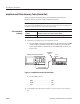
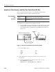
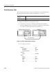
a. Hook up the oscilloscope: Connect the AWG500–Series Waveform
Generator CH1 output connector and the oscilloscope CH1 input
connector through the 50 W BNC coaxial cable and the SMA-to-BNC
adapter (see Figure 4–12).
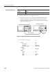
AWG500 Series Waveform Generator
Oscilloscope (TDS820)
50 W coaxial cable
SMAĆtoĆBNC
adapter
Figure 4-12: Direct DA out pulse rise time initial test hookup
b. Set oscilloscope controls:
Vertical......................... CH1
CH1 coupling . ............... DC
CH1scale .................. 100mV/div
CH1 vertical position . .......... About 2.7 Div
Horizontal
Sweep . .................... 500ps/div
Trigger
Source . .................... CH1
Slope ......................
Level ...................... -250 mV
Mode . ..................... Auto
Check Pulse Rise Time