
User's Manual

Performance Verification
4-52
AWG510 & AWG520 Service Manual
Event Input and Enhanced Mode Tests
These procedures check the event input signals and enhanced mode operation.
. The event input check with strobe off and strobe input check are struc-
tured as a continuous test. After Check Event Input with Strobe Off, the next test
uses the connections and oscilloscope settings from the last test.
Equipment
required
A 50ĂΩ coaxial cable, an oscilloscope, and customĆmade ground
closure.
Prerequisites The AWG500-Series Waveform Generator must meet the prerequisites
listed on page 4-13.
1. Install the test hookup and set test equipment controls:
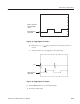
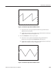
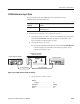
a. Hook up the oscilloscope: Connect the AWG500–Series Waveform
Generator CH1 output connector through the coaxial cable to the
oscilloscope CH1 input connector (see Figure 4–21).
Oscilloscope
50 W coaxial cable
AWG500 Series Waveform Generator
Figure 4-21: Event input and enhanced mode initial test hookup
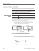
b. Connect the ground closure: Connect the ground closure to the EVENT
IN connector on the AWG500–Series Waveform Generator rear panel.
c. Set the oscilloscope controls:
Vertical . ........................ CH1
CH1 coupling . ............... DC
CH1 scale . ................. 0.2V/div
CH1 input impedance . ......... 50W
Horizontal
Sweep . .................... 0.5ms/div
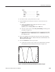
Check Event Input with
Strobe Off