
User's Manual

Performance Verification
AWG510 & AWG520 Service Manual
4-61
External Clock Input Tests
These procedures check the External clock input function of the AWG500–Series
Waveform Generator.
Equipment
required
Two 50ĂΩ coaxial cables, an adapter (N male to BNC femal), a signal
generator, and an oscilloscope.
Prerequisites The AWG500-Series Waveform Generator meets the prerequisites
listed on page 4-13.
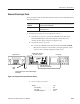
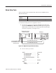
1. Install the test hookup and set test equipment controls:
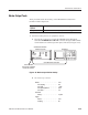
a. Hook up the oscilloscope: Connect the AWG500–Series Waveform
Generator CH1 output connector through the coaxial cable to the
oscilloscope CH1 input connector (see Figure 4–30).
b. Hook up the function generator:
Connect the AWG500–Series Waveform Generator EXT CLOCK
IN connector through a coaxial cable to the signal generator output
connector with a N–BNC adapter(see Figure 4–30).
Oscilloscope
Connect the cable to the EXT CLOCK IN connector through the
N-BNC adapter.
N-BNCĂĂ
Adapter
Connect the cable to the CH1
output connector on the front panel
AWG500 Series Waveform
Generator rear panel
Signal Generator
Figure 4-30: External clock input initial test hookup
c. Set the oscilloscope controls:
Vertical . ........................ CH1
CH1 coupling . ............... DC
CH1 scale . ................. 0.2V/div
CH1 input impedance . ......... 50W