
User's Manual

Adjustment Procedures
AWG510 & AWG520 Service Manual
5-3
Equipment Required
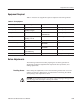
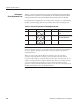
Table 5–2 lists the test equipment required to adjust the waveform generator.
Table 5-2: Test equipment
Item description Minimum requirements Example Purpose
1. Oscilloscope Bandwidth > 500 MHz Tektronix TDS784 Output signal adjustments
2. Frequency counter 1 MHz to 10 MHz
Accuracy < 0.2 ppm
Anritsu MF1603A Output signal adjustments
3. Spetrum analizer 1 KHz to 1 GHz Tektronix 497P or
Advantest R4131
Output signal adjustments
4. Digital multi meter DC volts range: 0.05 V to 10 V,
Accuracy: "0.1 %
Fluke 8842A Check voltage.
5. BNC cable Impedance 50 Tektronix part 012-0482-00 Signal interconnection
6. BNC to N adaptor BNC female to N male Tektronix part number
103Ć0045Ć00
Signal interconnection
7. DC block N type, 50 Tektronix part number
015Ć0509Ć00
DC block
8. Adjustment Tool Less than 1/8 inch diameter and
over 4 inches long
Manual adjustments
9. Fan Cooling the waveform generator
Before Adjustments
The following instructions describe preparing the waveform generator for
adjustment, loading the adjustment file required for these procedures, and
making adjustments.
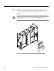
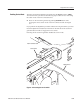
Before doing the adjustments, remove the waveform generator rear cover and
cabinet. See section 6, Maintenance, for instructions on removing the cabinet
and replacing it after adjustment is done.
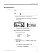
To avoid damaging the eject button, remove the floppy disk (if present)
from the floppy disk drive before removing the cabinet.
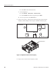
Providing Access