
User's Manual

Adjustment Procedures
5-6
AWG510 & AWG520 Service Manual
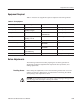
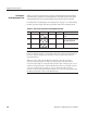
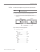
Table 5–3 lists the waveform files provided on the Performance Check/Adjust-
ment disk that is required to do the adjustments. The table lists the front-panel
settings that the file sets up and the adjustment procedures that use the files.
For instructions on loading files, see Loading Files on page 4–15. After loading
the files, press the floppy disk drive eject button and remove the floppy disk.
Table 5-3: File List for Performance Check/Adjustment Disk
No. File Name Wfm Shape Wfm Point Clock Usage
1 MODE.WFM 1000 1 GHz Clock frequency adjustĆ
ment
2 TRI512.PAT 512 1 GHz Clock duty adjustment
DAC delay adjustment
3 TRIM.PAT 480 10 MHz DAC linearity adjustment
. The files on the Performance Check/Adjustment disk are locked (the files
names are displayed with *), so the data in these files cannot be changed unless
the lock is opened. The file data includes not only waveform data, but also
output parameters.
When you select a file with the Waveform Sequence item, the waveform
generator output parameters change to those specified in the file, and the
waveform output reflects waveform data in the file. After selecting a file, do not
change an output parameter with the SETUP menu unless a procedure instructs
you to do so. During the procedures, if you are unsure that the waveform
generator settings still match the file’s settings, select the waveform again using
the Waveform Sequence item on the SETUP menu.
Performance
Check/Adjustment Files