
User's Manual

Adjustment Procedures
AWG510 & AWG520 Service Manual
5-9
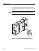
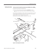
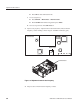
This procedure adjusts R5004 on the A50 AWG board to set the clock duty of
the AWG circuits. See Figure 5–6 on page 5–11 for the adjustment location .
Equipment
Required
One oscilloscope (Item 1)
One 50 coaxial cable (Item 5)
1. Install test equipment connections and set test equipment controls:
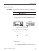
a. Connect the oscilloscope: Connect the AWG500 CH 1 output connector
through a BNC coaxial cable to the CH 1 input connector on the
oscilloscope.
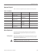
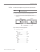
50 coaxial cable
AWG500 Oscilloscope
Figure 5-5: Hookup for the clock duty adjustment
b. Set oscilloscope controls:
Vertical . ........................ CH1
CH 1 coupling . ............... DC
CH 1 scale . ................. 0.2V/div
CH 1 input impedance . ......... 50
Horizontal
Sweep . .................... 100ns/div
Trigger
Source . .................... CH1
Coupling . ................... DC
Slope ...................... Positive
Level ...................... 0V
Mode . ..................... Auto
Clock Duty