
User's Manual

Adjustment Procedures
5-12
AWG510 & AWG520 Service Manual
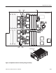
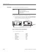
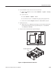
This procedure adjusts variable delay setting on the A50 AWG board for
theDAC clock timing. See Figure 5–6 on page 5–11 for the adjustment location.
Equipment
Required
One oscilloscope (Item 1)
One 50 coaxial cable (Item 5)
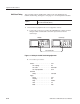
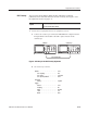
1. Connect the test equipment and set test equipment controls:
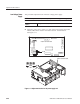
a. Connect the oscilloscope: Connect the AWG500 CH 1 output connector
through a BNC coaxial cable to the CH 1 input connector on the
oscilloscope.
50 coaxial cable
AWG500 Oscilloscope
Figure 5-7: Hookup for the DAC clock timing adjustment
b. Set oscilloscope controls:
Vertical . ........................ CH1
CH 1 coupling . ............... DC
CH 1 scale . ................. 200mV/div
CH 1 input impedance . ......... 50
Horizontal
Sweep . .................... 100ns/div
Trigger
Source . .................... CH1
Coupling . ................... DC
Slope ...................... Positive
Level ...................... 0V
Mode . ..................... Auto
DAC Clock Timing