
User's Manual


Removal and Installation Procedures
6-44
AWG510 & AWG520 Service Manual
Procedures for InnerĆChassis Modules
You should have completed the Access Procedure (page 6–16) before doing any
of the procedures for the Inner-Chassis modules. The procedures are presented in
the following order:
CPU Unit
CPU Board
Hard disk and Flash disk
LAN Board
A30 GPIB Board
Back Plane Board
Display Assembly and Supply Fuse
Front Subpanel
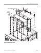
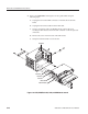
This procedure describes how to remove these circuit boards contained in the
CPU unit:
CPU Board
Hard disk and Flash disk
LAN Board
A30 GPIB Board
Back Plane
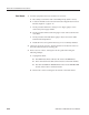
1. Assemble equipment and locate modules to be removed:
a. Have handy a screwdriver with a size Phillips #2
tip (Items 1 and 3).
b. Locate the modules to be removed in the locator diagram, Internal
Modules, in Figure 6–4, page 6–15.
c. Do the procedure A10/A11 Connector Board (page 6–39) to remove the
interconnect cables to the CPU board and the A30 GPIB board. It is not
necessary to pull the Connector board out.
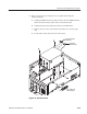
2. Orient the waveform generator: Set the generator so its bottom is down on
the work surface and the right side facing you.
CPU Unit