
User's Manual


Removal and Installation Procedures
6-50
AWG510 & AWG520 Service Manual
. The display and the display-driver board are a single module and must be
removed and replaced as such. They are listed as a single module in the
Replaceable Parts List.
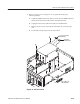
1. Assemble equipment and locate modules to be removed: Have handy a
screwdriver with a size Phillips #2
tip (Items 1 and 3). Locate the modules to
be removed in the locator diagram Inner-Chassis Modules, Figure 6–4, on
page 6–15.
2. Orient the waveform generator: Set the generator so its bottom is down on
the work surface and its rear is facing you.
3. Remove the high-voltage fuse: If you are servicing this fuse, remove the fuse
from its fuse holder. Reverse the procedure to reinstall.
Display tube handling: Use care when handling a display tube. If you
break a display tube it may implode, scattering glass fragments with high
velocity and possibly injuring you. Wear protective clothing, including safety
glasses (preferably a full-face shield). Avoiding striking the display tube with or
against any object.
Display tube storage: Store the display tube face down in a protected location,
placing it on a soft, nonabrasive surface to prevent scratching the face plate.
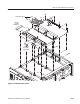
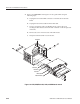
4. Remove the display tube:
a. Take the precautions outlined in the warning above. See Figure 6–24
while doing the following substeps.
b. Unplug the display tube connector from the back of the display tube and
the display tube yoke connector from the display circuit board (J340).
Loosen the screw on the video board that holds the CRT sockets. Then
pull back on the video board slightly. This separates the board from the
socket.
c. Remove the two screws that secure the band circling the front of display
tube to the front subpanel. Carefully guide display tube forward to
partially remove it from the front subpanel and to access the anode lead
connected to the display tube.
Display Assembly and
Supply Fuse