
User's Manual


Removal and Installation Procedures
AWG510 & AWG520 Service Manual
6-53
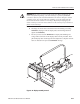
6. Reinstallation:
a. Do, in reverse order, substeps 5a–5b, reversing each step to reinstall
Display-Driver board.
b. Do, in reverse order, substeps 4a–4e, reversing each step to reinstall the
display tube if removed.
c. See step 3 to reinstall the supply fuse if it was removed.
d. See the following procedures, in order, to complete reassembly of the
waveform generator:
A10/A11 Connector Board (page 6–34)
Display-Frame Assembly
Trim Ring, Menu Buttons, and Output Panel (page 6–23)
Cabinet (page 6–20) (completes reassembly)
1. Assemble equipment and locate modules to be removed:
a. Have handy a screwdriver with a size Phillips #2
tip (Items 1 and 3).
b. Do the procedure Display Assembly and Supply Fuse (page 6–50). Do
not remove the display-driver board.
c. Locate the modules to be removed in the locator diagram Inner-Chassis
Modules, Figure 6–3, page 6–14.
2. Orient the waveform generator: Set the generator so its rear is down on the
work surface and its bottom is facing you.
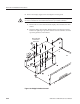
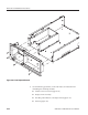
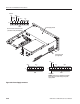
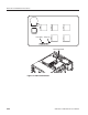
3. Remove the front subpanel: Remove the six screws securing the front
subpanel to the main chassis. (See Figure 6–26 for screw locations.) Lift the
front subpanel up away from the main chassis to complete the removal.
4. Reinstallation: Do the following substeps to reinstall the front subpanel and
reassemble the remainder of the generator:
a. Align the front subpanel to the main chassis, taking care to ensure that
the main chassis slips into its alignment slot on the front subpanel (see
magnified view, Figure 6–26.) Then reinstall the six screws removed in
step 3.
b. See the procedure Display Assembly and Supply Fuse (page 6–50) to
reinstall the display-frame assembly and display tube.
Front Subpanel