
User's Manual

Performance Verification
AWG510 & AWG520 Service Manual
4-5
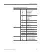
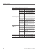
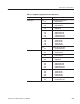
See Table 4–1 for details on error codes.
3. Return to regular service: Push any bottom or menu button (other than
UTILITY) to exit the diagnostic screen.
The instrument includes internal calibration routines that check electrical
characteristics such as offset, attenuations and filters. Perform calibration to
adjust internal calibration constants as necessary. This procedure describes how
to do the internal calibration.
Equipment
required
Prerequisites
_ _
1. Confirm that no output is performed: Confirm that the RUN LED does not
light. If not, push the RUN button so that the RUN LED goes off.
. When you start calibration while the output is being performed, some
calibration items may be failed.
2. Verify that internal adjustments pass: Do the following substeps to verify
passing of internal adjustments.
a. Run the adjustments routine: Push UTILITY (front panel)Diag
(bottom) Execute Calibration (side). This executes the AWG500
calibration routines automatically.
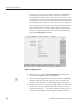
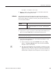
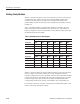
b. Wait: The internal calibration does an exhaustive verification of proper
AWG500 function. While this verification progresses, the message box
displaying Executing Calibration appear on screen. When finished, the
resulting status will appear in the message box as shown in Figure 4–2.
Calibration