
User's Manual

Performance Verification
AWG510 & AWG520 Service Manual
4-25
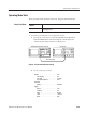
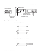
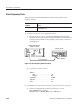
Oscilloscope
Connect the cable to the CH1
output connector on the front-panel
Connect the cable to the
TRIG IN connector through
the BNC T adapter.
Connect the cable to the TRIG IN
connector through the BNC T adapter.
BNC T
Adapter
AWG500 Series Waveform
Generator rear panel
Function Generator (AFG310)
Figure 4-6: Triggered mode initial test hookup
c. Set the oscilloscope controls:
Vertical . ........................ CH1andCH2
CH1 coupling . ............... DC
CH1scale .................. 0.2V/div
CH2scale .................. 2V/div
CH1 input impedance . ......... 50W
CH2 input impedance . ......... 1MW
Horizontal
Sweep . .................... 500ns/div
Trigger
Source . .................... CH1
Coupling .................... DC
Slope ...................... Positive
Level ...................... +100 mV
Mode . ..................... Auto
d. Set the function generator (AFG310) controls:
Function ........................ Square
Mode .......................... Continuous
Parameters
Frequency .................. 400kHz
Amplitude . .................. 2.0V(4Vinto open circuit)
Offset . ..................... 1.0V(2Vinto open circuit)
Output . ........................ Off