
User's Manual

Performance Verification
4-26
AWG510 & AWG520 Service Manual
2. Set AWG500–Series Waveform Generator controls and select the waveform
file:
a. Initialize the AWG500–Series Waveform Generator controls:
Push UTILITY (front–panel)
System (bottom)Factory Reset (side)OK (side).
b. Set triggered mode: Push SETUP (front–panel)Run Mode (bot-
tom)Triggered (side) to set the AWG500–Series Waveform Generator
to triggered mode.
c. Select the file: Load the MODE.WFM as referring to the procedures on
page 4–15.
3. Turn on the AWG500–Series Waveform Generator CH1 output: Push the
RUN and CH1 OUT buttons so that the LEDs above the RUN button and
CH1 output connector light.
4. Check triggered mode with manual triggering: Push the AWG500–Series
Waveform Generator FORCE TRIGGER button and check that when the
button is pushed, the oscilloscope displays a one-cycle sine wave.
5. Check triggered mode with external triggering:
a. Enable function generator output: Turn on the function generator output.
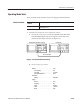
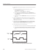
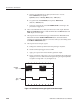
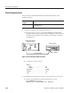
b. Check triggering: Check that for each trigger supplied by the function
generator, the oscilloscope displays a one-cycle sine wave (see Figure
4–7).
Figure 4-7: Relationship between trigger signal and waveform output