Copyright © Tektite, Inc, 1995, All rights reserved. Tektite products are covered by U.S, and foreign patents, issued and pending, Information in this publication supersedes that in all previously published material. Specifications and price change privileges reserved, Printed in the U.S.A. Tektite, Toc, PO, Box 1000, Jacksonville, OR 97070-1000 TEKTITE and TEAK are registered wade marks of Tektite, Inc.
WARRANTY Tektite warrants that this product will be free from defects in materials and workmanship for a period of three (3) from the date of shipment. If any such product proves defective during this warranty period, Tektite, at its option, either will repair the defective product without charge for parts and labor, or will provide a replacement in exchange for the defective product.
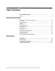
Table of Contents General Safety Summary Preface .. Performance Verification Performance Verification Procedures vegan Conventions Brief Procedures Self Tests Functional Te: Performance Tests Prerequisites . Equipment Required .
Table of Contents List of Figures Figure I-1: Map of Display Functions -3 reifying Adjustments and Signal Path Compensation 1-6 : Universal Test Hookup for Functional Tests . 1-8 Figure 14 Initial Test Hookup 1-20 Figaro 1-5: Initial Test Hookup 1-23 Figure 1-6: Initial Test Hookup Lo 126 Figure 1-7: Measurement of Analog Bandwidth 129 Figure 1-8: Initial Test Hookup 1-31 Figure 1-9: Measurement of Channel Delay .
of Contents List of Tables Table 1-1; Test Equipment 1-16 Table 1-2: DC Offset Accuracy F 1-22 : Analog Bandwidth (TDS 410A and TDS 4204A) 1-27 Table 1-4: Analog Bandwidth (TDS 460A) 128 Table Key Features of the TDS 400A Oscilloscopes 2-1 Table 2-2: Nominal Traits — Signal Acquisition System 2-3 Table 2-3: Nominal Traits — Time Base System Table 2~4: Nominal Traits — Triggering System "Table 2-5: Nominal Traits — Display System .
General Safety Summary Review the following safety precautions to avoid injury and prevent damage (o this product or any products connected to it Only qualified personnel should perform service procedures. Injury Precautions Use Proper Power Cord To avoid fire hazard, use only the power cord specified for this product. Avoid Electric Overload o avoid electric shock or fire hazard, do not apply 2 voltage (o a terminal that is outside the range specified for that terminal.
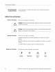
General Safety Summary Do Not Operate With If you suspect there is damage to this product, have it inspected by qualified Suspected Failures service personnel. Safety Terms and Symbols Terms in This Manual These terms may appear in this manual: WARNING. Warning statements identify conditions or practices that could result ! in injury or loss of life. ! CAUTION. Caution statements identify conditions or practices that could result in : damage to this product or other property.
Preface Related Manuals This is the Performance Verification for the TDS 410A, TDS 4204, and TDS 460A Oscilloscopes, It contains procedures suitable for determining if the oscilloscope functions, is adjusted properly, and meets the performance characteristics as warranted. Also contained in this document are the specifications for the TDS 400A Digitizing Oscilloscopes. The following documents relate to the use or service of the digitizing oscilloscope.
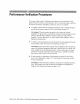
Performance Verification Procedures Two types of Perform an Verification procedures an be performed on this product: Brief Procedures and Performance Tests. You may not need to perform all of these procedures, depending on what you want to accomplish: “To rapidly confirm (hat this oscilloscope functions and is adjusted properly, just do the procedures under Self Tests, which begin on page 1-5.
Performance Ve Conventions Throughout these procedures the following conventions apply: ® Each test procedure uses the following general format: Title of Test Equipment Required Prerequisites Procedure % Each procedure consists of as many steps and sub steps as required to do the test. Steps and sub steps are sequenced as follows: 1. First Step a. First Sub step b, Second Subside 2.
Brief Procedures Self Tests Verify Internal Adjustment, Self Compensation, and Diagnostics The Self Tests use internal routines to confirm basic functionality and proper adjustment, No test equipment is required to do these test procedures. The Functional Tess use the probe-adjust output at the front panel as a test signal source for further verifying that the oscilloscope functions properly. A standard-accessory probe, included with this oscilloscope, is the only equipment required.
Brief Procedures Caspian the CAL menu. 1-6 e, Confirm the four adjustment sections have passed swats: ® Press SHIFT; then press UTILITY. #® Press the main men bunion System until Cal is highlighted in the pop-up menu. ® Verify that the word Pass appears in the main menu under the following men labels: Voltage Reference, High Frequency Response, Low Frequency Response, and Trigger Skew. (See Figure 1-2.) Tek Run: 1.
Brief Procedures You must run an SPC anytime you wish to ensure that the measurements you wake are made with the most accuracy possible. You should also run an §PC if the temperature has changed more than 5° C since the last SPC was performed. . Run the signal path compensation: Disconnect all input signals. Press the main-menu button Signal Path; then press the side-menu bunion OK Compensate Signal Paths, NOTE.
Brief Procedures STIR These procedures verify fun Features operate. They do not ver ions; that is, they verify that oscilloscope that they operate within limits. Therefore, when the instructions in the functional tests that follow call for you to verify that a signal appears on screen “that is about five divisions in amplitude” or “has a period of about six horizontal divisions.” and so forth., do NOT interpret the quantities given as limits.
S b, [Initialize the oscilloscope: ® Press frenetically SETUP. B Press the main-menu button Recall Factory Setup. ® Press the side-menu button OK Confirm Factory Nit. Verify that all input channels opera CH | first, skipping sub step d sin : Do the following subsides — test CH ] is already set up for verification from step 1. a. Sleet an unverified channel: ® Press WAVEFORM OFF to remove from display the channel just verified, ¥ Press the front-panel button that corresponds to the channel you are to verify.
Brief Procedures A Verify the Time Base 1-10 d. €. Verify that the channel acquires in all acquisition modes: Press SHIFT, then press ACQUIRE MENU. Use the side menu to select, in turn, each of the five hardware acquire modes and confirm that the following statements are true. Refer to the icons at the left of each statement as you confine those statements. = Sample mode displays an actively acquiring waveform on screen. {Note that there is noise present on the peaks of the square wave.
® Press VERTICAL MENU. ® Press the main-menu button Bandwidth. Then press the side-menu button 20 MHz. ® Press CLEAR MENU to remove the vertical menu from the screen. 2. Verify that the time base operates: Confirm the following statements. a. One period of the skate-wave probe-compensation signal is about five horizontal divisions on-screen for the 200 ys horizontal scale sifting {set in step Te) b.
Brief Procedures ® Press the main-menu bunion Bandwidth; then press the side-menu button 20 MHz. ® Press TRIGGER MENU. m Press the main-men button Mode & Hold off. ® Press the side-men bunion Normal. ® Press CLEAR MENU to remove the menus from the screen. o that the main trigger system operates: Confirm that the following statements are true. ® The trigger-level readout for the main trigger system changes when you rotate the trigger MAIN LEVEL knob.
Verify the File System Brief Procedures ® Pressing the side-menu button Set to 50% triggers the probe-compensation signal that you just left triggered. (Leave the signal triggered.) Verify the delayed trigger counter: ® Press the main-menu button Delay by Time. ® Press the side-menu button Events, just below the Trigger able after Time selection. M Use the General Purpose knob to enter an event count of 325 events.
1-14 Set the horizontal SCALE to 500 us, and then use the vertical POSITION knob to place the channel { baseline trace two divisions above fencer serene, Press the main menu button Recall Saved Setup; then press the side menu button From File. Turn the general purpose knob to select the file 1 recall. For paraplegia, if vou followed the instructions above and nosed a blank di digitizing oscilloscope assign the name TEXG0060.
Performance Tests Prerequisites Related Information This section contains procedures for checking that the TDS 400A Digitizing Oscilloscopes perform as warranted, The procedures are arranged in four logical groupings: Signal Acquisition System Checks, Time Base System Checks, Triggering System Checks, and Output Ports Checks. They check all the characteristics that are designated as checked in Chapter 2, Specification.
Table 1-1: Test Equipment {Cont.} Performance Tests Hem Number and Description Minimum Requirements Example Purpose 17. Probe, 10X included with | A PP6138 probe Tektite P6138 Signal Interconnection this oscilloscope 18, Generator, Video Signal | Provides SCENT compatible outputs Tektite T8G 1001 Checking Video Trigger Sensitivity ' I available, items 11,12, 13, and 15 can be replaced by a Tektite SG 503 and $G 504. If available, a TG 501A may be used to check Sample-Tate and Delay-time Accuracy.
Performance Tests Test Record Photocopy this and the next page and use them to record the performance test results for your oscilloscope. TDS 400A Test Record Oscilloscope Striated Number: Temperature: Certificate Number: RH %: Date of Calibration: Technician: Performance Test Minimum incoming Outgoing Maximum Offset Accuracy CH1 Offset {41005V 410V 9935V {410,065V +99.9V 992805y +100.5498 V CH2 Offset #1¥ 1895 my +1.005Y +10V +10.088 Y 999V + 1005495 V CH3 Offset Sy 995 ~1008Y (TS 420A & oV 8938V +10.
Performance Tests Signal Acquisition System Checks These procedures check those characteristics that relate o the s band ave listed as checked under Warranted Characteristic Chapter 2, Specifications. signal-acquisition Check Offset Accuracy Equipment Two dual-banana connectors {item 7) Required quire One BNG T connector {tem 8) One DG calibration generator {item 10) Two precision coaxial cables {stem 5) Prerequisites The oscilloscope must meet the prerequisites sifted on page 1-15 1.
Performance Tests b, Initialize the oscilloscope: Press frenetically 'UP. Press the main-menu bunion Recall Factory Setup. Press the side-menu button OK Confirm Factory Nit, ¢ Modify the default settings: 2. Confirm input channels are within limits for following sub steps Set the horizontal SCALE to 1 ms. Press SHIFT, then ACQUIRE MENU. Press the main-menu button Medea; then press the side-menu button Hi Res. Press DISPLAY. Press the main-menu button Articulate; then press the side-menu button Frame.
Table 1-2: DC Offset Accuracy Vertical Vertical ; Generator Offset Scale Setting Position Offset Setting | Setting Accuracy Limits Roomy ¢ 10y HOV sy v o +99.9V +99.8V [+ b, Set the vertical scale: Set the vertical SCALE to one of the settings listed in Table 1-2 that is not yet checked. (Start with the fires setting listed.) ¢ Set the offset: Press the VERTICAL MENU button and then the Offset main-menu button, Using the General Purpose knob, set the offsets dictated by Table 1-2.
Performance Tests 1. Install the test hookup and preset the instrument controls: a. Du gt Banana o BNC Adapters Hook up the test-signal source: Output Sense N \\ DG Calibrator Set the output of a DC calibration generator to (f volts.
Performance Tests Press MEASURE. Press the main-menu button Select Measurement for CHx; then press the side-menu button Mean. (You will nave to press MORE several times to access the Mean measurement.) Set the vertical SCALE to 100 mV. Press the VERTICAL MENU button and then the Offset main menu button, Set the offset w0 O V.
Performance e. Check against limits: Do the following subpart in the order listed. ® Use this formula to calculate voltage measurement accuracy. 700 mV (mean from step ¢ — (present mean)) For example: 700 mV — {347 mV (358 mV) =-S5 mV ® CHECK that the voltage measurement accuracy is within & 20.8 mV. f. Test all channels: Repeat sub steps a through e for all channels. 3. Disconnect the hookup: a. Set the generator output Then disconnect the cable from the g connector of the channel last tested.
Performance Tests 1-26 w Press SHIFT; then ACQUIRE MENU, ® Press the main-menu button Mode: then press the side-menu button Average 16, ® Press Measure. Now press the main-menu button High-Low Setup; then press the side-menu button Min-Max. Sine Wave Digitizing Oscilloscope Generator Sl ¥ r Figure 1-6: Initial Test Hookup NOTE. Refer 1o the Sine Wave Generator Leveling Procedure on page 1-55 if your sine wave generator does not have automatic output amplitude leveling. €.
b. Mate the trigger source to the channel selected: m Press TRIGGER MENU. # Press the main-menu button Source. W Press the side-menu button their corresponds to the channel selected. Set the input impedance of the channel: ® Press VERTICAL MENU; then press the main-menu button Coupling. W Press the side-menu button €2 to toggle it to the 50 Q suing, Set the vertical scale: Set the vertical SCALE tw one of the settings sifted in Table 1-3 (TDS 410A and TDS 420A) or Table 1-4 (TDS 460A) not yet checked.
Performance Tests Table 1-4: Analog Bandwidth (TDS 4604) Vertical Scale Reference Amplitude Horizontal Scale Test Frequency Limits 100 mvV 600 mV {8 divisions) 2ns 400 MHz 2424 divisions) 2ns 400 MHz >1.
Read the results from the readout o! 3 measurement Pk-Pk, Set the generator frequency to the test frequency from rabies 1-3 and -4, Set the horizontal s 2 scale from the tables. Performance Tests ® Read the results at the CHx Pk-Pk readout, which automatically measures the amplitude of the test signal. (See Figure 1-7.
Performance Costs NOTE. Passing the signal path compensation confirms the signal path for all vertical scale settings for all channels. Passing the internal diagnose that the factory-set adjustment constants that control the bandwidth for each vertical scale setting have not changed.
Performance Tests b, Modify the initialized front-panel control settings: ® Do not adjust the vertical position of uny channel during this procedure. ®m Set the horizontal SCALE Press SHIFT; then press ACQUIRE MENU. = Press the main-menu button Mode, and then press the side-menu button Average 16. ¢ Hook up the rest-signal source: ® Connect the sine wave output of a sine wave generator precision coaxial cable, a 50 termination, and a dual-input couplet.
Performance Tests <. If you are testing a TDS 410A, skip to step h. d. Save a CH 3 waveform: Move the couplet from that CH 1 and CH 3 are driven. Press CH 3; then press the side-menu Hutton To Ref 3. Display all rest signals: Press WAVEFORM OFF twice to remove CH 2 and CH 3 from the display. Move the couplet from that CH | and CH 4 are driven. Press CH 4 to display. Now, press the front-panel button MORE. Press the main-menu buttons Ref 2 and Ref 3.
Performance Read the resits here. Display the liver reference waveform for aft foi petards of the waveform. Identify the ims reference 2 / Turn on the cursor and align P the V bar cursors 1o the dime 3 = reference points, T ene tomato ooy 10608 Figure 1-9: Measurement of Channel Delay b, Check and against limit: ® Press WAVEFORM OFF four times to remove all waveform. ® Preschool 8 Press MORE; then press the main-men bunion Ref 2.
Performance Tests 3. Disconnect the hookup: Disconnect the cable from the generator output at the input connectors of the channels. Time Base System Checks Check Accuracy for Long-Term Sample Rate, Delay Time, and Delta Time Measurements 1-34 These procedures check those characteristics that relate to the Main and Delayed ume base system and are listed as checked under Warranted Characteristics in Chapter 2, Specifications.
Performance Tests ¢ Modify the initialized front-panel control settings: Press VERTICAL MENU; then press the main-menu button Coupling. Press the side-menu button © 1o change the coupling setting necessary, set the vertical SCALE to 100 mV per division Set the horizontal SCALE of the Main time base to 2.0 ns. Using external enumerators if nieces amplitude for division display v, adjust the time standard Rotate the vertical POSITION control to center the displayed waveform. 2.
Performance Tests 1-36 Set the frequency of the time standard to 1.0 MHz (or a period of 1.00 ps). Adjust the amplitude of the time standard fora 51w 7 division display. Press CLEAR MENU, Press SET LEVEL TO 50%. Rotate the horizontal and vertical POSITION controls to move the rising edge of the waveform so that it crosses the center of both the horizontal and vertical articulate fines. Press HORIZONTAL MENU; then press the main-menu button Time Base.
Performance Tests Creek tart ihe waveform fusing i edge is within £0.5 horizon! Time: 19,8045 ‘ visions on the center ¥ 1| horizontal articulate Deceived T (0o W guns G DNA Trig i I P3N Wi { Ges Bettye otz | oz | Cork | 1 ironstone | lag tin | blithe | W | metier olo) Enter & 10.0 s delay and set the horizontal scad for the D time base 1o 100 ns. Figure 1-11: Measurement of Accuracy — Long-Term and Delay-Time B Set the horizontal SCALE of the D (delayed) time base to 500 us.
Performance 'Tests Trigger System Checks These procedures check those characteristics that relate to the Main and Delayed trigger systems and are listed as checked winder Warranted Characteristics in Chapter 2, Specifications. Check Accuracy, Trigger Equipment One DC calibration generator (stem 10} Level or Threshold, DG Required One BNC T connector (fem &) Coupled Two precision coaxial cables (fem 5} Prerequisites The oscilloscope must meat the prerequisites listed on page 1-15 L.
Performance & Press the main-menu button Recall Factory Setup. #& Press the side-menu button OX Confirm Factory Nit. 2. Confirm Main trigger system is within limits for BACCHIC! a. Display the rest signal: ™ Set the vertical SCALE Set the standard output of a DC calibration generator to +0.3 V. b, Measure the test signal: = Press SET LEVEL TO 50%.
b. Select the Delayed trigger system: ® Press SHIFT; then press the front-panel button DELAYED TRIG. ® Press the main-menu button Level. ¢, Measure the test signal: Press the side-menu button SET TO 50 % Read the measurement results in the side menu below the label Level. d. Check against limits: Do the following subpart in the order listed. ® Subtract the trigger level readout from the DC calibration generator setting. The result is the trigger level accuracy.
Performance Tests b, Modify the initialized front-panel control settings: ® Set the horizontal SCALE for the M (main) time base Press HORIZONTAL MENU: then press the main-men button Time Base. ™ Press the side-menu baton Delayed Only; then press the side-menu button Defrayed Trigger able. m Sct the horizontal SCALE for the D (delved) time base to 20 ns; then press the side-menu button Main Only. ® Press TRIGGER MENU; then press the main-menu button Mode & Hold off. Now press the side-menu button Normal.
Performance Tests & Press the rain-menu button High-Low Setup: then press the side-menu bunion Min-Max, o Press the main-menu bunion Select Measurement for Chi. & Press the side-menu button ~-more— until Amplitude appears in the side menu (its icon is shown at the left). Press the side-menu button Amplitude. » Adjust the trigger MAIN LEVEL knob to obtain stable triggered waveform, = Press CLEAR MENU. B Set the test signal amplitude for about three and a half divisions on screen.
trigger sensitivity. Check for a stable trigger at both the passive and ive slope settings, 2~ TDS 410A, TDS 420A & TDS 460A Performance Verification and Specifications Performance Tests Kuf 2500505 ¢4 Average pid GEE ed eve M2.0ms Chi T By :M*‘ Eve T
Performance Tests b, Set the Main and Delayed Horizontal Scales: & Set the horizontal SCALE te 5 ns for the M (Main) time base, = Press the side-mean button Delayed Only. & Set the horizontal SCALE to 2 ns for the D (Delayed) time base. Press the side-menu button Main Only. <. Display the test signal: W Set the generator frequency to 350 MHz (TDS 410A and TDS 420A) or 300 MHz (TDS 460A). ® Set the test signal amplitude for about five divisions on screen.
Performance Tests Press the main-menu bitten Recall Factory Se tap. Press the side-menu button OK Confirm Factory Nit, b, Modify the initialized front-panel control settings: Set the vertical SCALE 10 1 vol: set the horizontal SCALE to 20 vs, Press VERTICAL MENU, Pres the main-menu button Coupling. Press the side-menu button Q to toggle it to the S0 Q setting. Press TRIGGER MENU.
Performance Te NOTE. Refer 1o the Sine Wave Generator Leveling Procedure on page 1-55 if our sine wave generator does not have automatic output amplitude leveling. 2. Confirm the Trigger input: a. Display the test signal: B Set the generator for a 10 MHz, four division signal, b.
Performance Tests Check Video Trigger Equipment Scone format video generator {stem 18) Sensitivity Required Option 05 Equipped Mode o e Is Only) One 75 O terminator {inert 4) Ore 75 () coaxial cable (item 6} Prerequisites See page 1~15 L. Install the test hookup and preset the oscilloscope controls: a. Initialize the oscilloscope: ® Press save/recall SETUP. *® Press the main menu button Recall Factory Setup, = Press the side menu button OK Confirm Factory Nit.
Performance 2. Confirm the video trigger system is within limits: a. Display the test signal: ® Set video generator (o SCENT format, % Set the output of the generator for a five step ramp with color burst, 8 Press SET TO 50%. Use the wiggler MAIN LEVEL knob o stabilize the display as required. ® Press TRIGGER ME ® Press the main menu button Medea & Hold off. Then press the side menu button Normal. b.
{ l p Adjust the sync purse oral amplitude for 0.6 divisions. Performance Tests i Rum: MVP Tasmania chis sV fine Scale: loamy sample Counting !P,amdwivzl& Position | offset Figure 1-18: Adjusting Sync Pulse Amplitude TDS 410A.
Performance Tests ® CHECK that a stable trigger is obtained with the last of TV field 1 and the beginning of TV field 2 displayed. (If the last line line duration (31.75 ps), then it is the end of field 1 — see waveform R2 in Figure 1-19.) ® Press the side memo button All. W Press the main weaken button Medea and Hold off. Then press the side memento button Hold off. ® Use the General Purpose knob to set the hold off to 1.
conformance Tests ® Press the side-menu button Odd. = Rotate the horizontal POSITION control counter clockwise and align the rigger “I” 1o center screen ¥ Press the main-menu button TV Delay Mode. m Press the side-menu button Line. ® Use the General Purpose knob to set the line count to 10, ® CHECK that the selected Heine is the first line that has the color burst signal. e, Check sync trigger: ® Using the Vertical POSITION knob, move the video waveform from the top to the bottom of the display.
Performance Tests b. Hook up the test-signal source: Sine Wave Generator Set the Vertical SCALE to 1 Volt per division, Connect the output of a function generator through a 50 & precision coaxial cable and a 50 ©Q terminator to the CH I input. Set the output of the function generator for a 5 MHz. 0 to 4 Volt (4 division) square wave at the oscilloscope input. Move the setup from the CH 1 input to the AUX TRIGGER/EXT CLOCK input on the rear panel of the oscilloscope (see Figure 1-20).
Performance Tests d. Check external clock: ® CHECK that the displayed sine wave has a one division period. u Slowly adjust the frequency of the function generator to 10 MHz while watching the display. ® CHECK that the period of the displayed sine wave changes to two divisions. ® Press CLEAR MENU. 2.
acne Tests Figure 1-21: Initial Test Hookup b, Initialize the oscilloscope: & Press frenetically SETUP & Press the main-menu Burton Recall Factory Setup. #® Press the side-menu button OK Confirm Factory Nit, ¢ Modify the initialized front-panel control settings: ® Press AUTO SET. Set the horizontal SCALE to 200 us. ® Press SHIFT; then press ACQUIRE MENU., ® Press the main-menu button Medea; then press the side-menu button i Res. 2.
Performance Tests B Press CLEAR M Figure 1-22. CNU to remove the menus from the display. See fl : i chi Am pi v i Soddy 1oooskil ERS TORT S WHITTIER o1 yut 2035 2234y Figure 1-22: Measurement of Probe Compensatory Limits b, Check against limits: CHECK that the CH 1 Freq readout is within 950 Hz 1o 1030 kHz, inclusive, and that the readout for Cht Am pl is within 473 mV 0 525 mV. inclusive. ¢ Disconnect the test hookup: Remove the test probe as desired.
Performance Tests Procedure for Best Equipment Accuracy Required Sine Wave Generator {item 11) Level Meter and Power Sensor {fem 12) Power Spinster {item 18} Two Mai N to Female BNC Adapters (tem 15} One precision coaxial cable (lem 5) Prerequisites See gaps 1~15 Sine Wave Generator Digitizing Oscilloscope Love Pier Splinter Figure 1~23: Sine Wave Generator Leveling Equipment Setup L. Install the fest hookup: Connect the equipment as shown in Figure 1-23.
Performance Tests W Input the correction factor for the new frequency into the level meter, ® Adjust the sine wave generator amplitude until the feel meter again reads the value noted in step 3. The signal amplitude is now correctly set for the new frequency. Alternate Procedure for Equipment Sine Wave Generator tem 11) i i Required Maximum Amplitude equal Tevet Meter and Power Sensor (em 12) Two Male N to Female BNG Adapters (tem 15} Two precision coaxial scabies {contemn 5) Prerequisites Ses page 1-15 1.
Performance Tests 1-58 Record the reference level: ® Disconnect the sine wave generator from the digitizing oscilloscope. ® Connect the sine wave generator to the power sensor. W Note the level meter reading, 4. Set the generator to the new frequency and reference level: #® Change the sine wave generator o the desired new frequency. & Input the correction factor for the new frequency into the level meter, ® Adjust the sine wave generator amplitude ulna the level meter again reads the value noted in step 3.
Specification This Chapter begins with a general description of the traits of the TDS 400A Digit sizing Oscilloscopes. Three sections follow, one for each of three ¢la traits: nominal traits, warranted characteristics, and typical character General The TDS 400A Digitizing Oscilloscopes are portable, four-channel instruments suitable for use in a variety of test and measurement applications and systems. Table 2-1 hosts key features.
Nominal Traits Nominal traits are described using simple statements of fact such as “Four, al} identical” for the trait “Input Channels, limits that are performance requirements. Number of.
Nominal Traits Table 2-2: Nominal Traits — Signal Acquisition System (Cont} Name Description Rise Time? Volts/Div Setting Rise Time (DS 4104 and TDS4204) 5 10 Vivid 17508 2 vivid 23315 1 vivid 3.88ns Rise Time? Volts/Div Setting Rise Time (TDS 4604) 5 Divided Vivid (875 ps 2 vivid 14ns 11 vivid 35ns * Displayed vertically with 25 digitization levels (DLs) per division and 10.
Nominal Traits Table 2-3: Nominal Traits — Time Base System Name Description Range, Sample-Rate’? 2.5 Samples/s to 100 Samples Range. Equivalent Time or Interpolated Waveform Rate?3 200 Samples to 30 Vampires Range, Seconds/Division 1 insidious to 20 siding Range, Time Base Delay Time 010 20 seconds Reference Frequency, Time Base 100 MHz Record Length Selection 560, 1,000, 2,500, 5,800, 15,000, and 30,000 points.
Nominal Traits Table 2-5: Nominal Traits — Display System Name Description Video Display Resolution 840 pixels horizontally by 480 pixels vertically in a display area of 5.04 inches horizontally by 3.78 inches vertically Waveform Display Articulate A wriggle articulate 401 x 501 pixels {8 x 10 divisions, with divisions that are 1 om by enemy Waveform Display Grey Scale 18 levels in variability-persistence display style Table 2-6: Nominal Traits — Data Sorta: ge Name Description Capacity.
Table 2-8: Nominal Traits — Mechanical Nominal Traits Name | Description Gosling Method Forced-ale consolidation with no air filter Construction Material Chassis parts constructed of aluminum alloy, front panel constructed of plastic laminate; circuit boards constricted of glass-laminate. Plastic parts are poly carbonate Finish Type Tektite Blue textured vinyl finish on aluminum cabinet Weight $Standard digitizing oscilloscopes 8.6 kg (1.0 tbs}, oscilloscope only 10.2 kg (22.
Nominal Traits Table 2-8: Nominal Traits — Mechanical (Cont.} Name Overall Dimensions 2-8 Description Standard digitizing oscilloscope Height 191 mm (7.5 in}, when feet and accessories pouch are instated. 165 mm {8.5 in}, without the accessories pouch installed Width 381 mm {15 In), with handle Depth 471 mm (18.55 i), oscilloscope only; 490 rmm (18.28 in, wih optional front cover installed; 569 mm {22.4 in), with handier fully extended Rack mount digitizing oscilloscope Height 178 mm (7.
Nominal Traits 3081 mm {12130y Figure 2-1: TDS 400A Dimensional Drawing 185 mm 50} 568 mm 381 mm {18in) TDS 4104, TDS 420A & TDS 460A Performance Verification and Specifications 2-8
Warranted Characteristics Performance Conditions This section lists the various warranted characteristics that describe the TDS 400A Digitizing Oscilloscopes. Included are electrical and environmental characteristics. Warranted characteristics are described in terms of quantifiable performance limits which are warranted. This section lists only warranted characteristics. A fist of typical characteristics starts on page 217, ) NOTE.
‘Warranted Characteristics Table 2-9: Warranted Characteristics ~— Signal Acquisition System (Cont.
Warranted Characteristics Table 2-9: Warranted Characteristics — Signal Acquisition System (Cont.) Name i Description Lower Frequency Limit, AG <10 Hz when AC-1 MO coupled; <200 kHz when AG-50 0 coupled? Coupled 1 See Analog on page 2-17 for the typical analog bandwidth with the standard-accessory probe. 2 Net Offset = Offset ~ (Position x Volts/Div), Net Offset is the voltage level at the center of the A-D converter dynamic range. Offset Accuracy is the accuracy of this voltage level.
ed Characteristic Table 2-11: Warranted Characteristics — Triggering System Name Description Accuracy, Trigger Level or Threshold, DC Coupled Sensitivity, Edge-Type Trigger, DC Coupled? +{2% of 1 Setting — Nt Offset!{ + 0.2 div x volition setting + Offset Accuracy) for any channel as trigger source and for signals having rise and fall times 2 20 ns 0.
Warrant characteristics Table 2-14: Warranted Characteristics — Environmental, Safety, and Reliability Name | Description Atmospherics Temperature: Standard instrument; Operating, 0° Cto +50° C; Non operating, ~40° G 10 +75° C instrument with Option 1F: Operating, +4° C 10 +50° C; Non operating, ~22° C to +60° C Option 3P: Operating.
Warring d Characteristics Table 2-14: Warranted Characteristics — Environmental, Safety, and Reliability {Cont.) Name Description Susceptibility Masts or exceeds the requirements of the following standards: ENB0082-1 European Community Requirements fEC 801-3 Radiated Susceptibility 3 Vi meter from 27 MMz to 500 MHz modulated Performance Criteria: < + 0.2 division waveform displacement, or < 0.
Typical Characteristics s section contains tables that list the various typical characteristics that be the TDS 400A Digitizing Oscilloscopes. Typical characteristics are described in terms of typical or average performance. Typical characteristics are not warranted. Tl tics starts on page 2-11. Table 2-15: Typical Characteristics — Signal Acquisition System subsection lists only typical characteristics.
Typical Characteristics Table 2-15: Typical Characteristics — Signal Acquisition System (Cont,) Name Description Step Response Settling Error Volts/Div Setting Step Amplitude Settling Error 20ns 500 ns 1 vivid =2V =05 0.2 100 avidity =20V 2.0 <05 1 Divinity-10 Vivid <200V 20 0.5 <02 The samples must be acquired under the same setup and ambient conditions.
Table 2~17: Typical Characteristics ~ Triggering System Name Description Error, Trigger Position, Edge Triggering Acquire Mode Trigger-Position Error'? Sample, Hi-Res.
Typical Characteristics Table 2-17: Typical Characteristics — Triggering System (Cont.} Name Description Width, Minimum Pulse and Rearm, Events [5ns Delay® 1 The trigger position errors are typically less than the values given here. These values are for triggering signals having a slew rate at the trigger point of 0.5 division ins, The waveform interval (Wi} is the time between the samples in the waveform record.