
User's Manual


Operating Basics
30
TDS1000/2000-Series Digital Oscilloscope User Manual
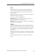
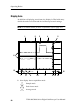
7. An arrow icon indicates that the waveform is inverted.
8. Readouts show the vertical scale fact ors of the channels.
9. AB
W
icon indicates that the channel is bandwidth limited.
10. Readout shows main time base setting.
11. Readout shows window time base setting if it is in use.
12. Readout shows trigger source used for triggering.
13. Icon shows sel ected trigger type as follows:
-- Edge trigger for the rising edge.
-- Edge trigger for the falling edge.
-- Video trigger for line sync.
-- Video trigger for field sync.
-- Pulse Width trigger, positive polarity.
-- Pulse Width trigger, negative polarity.
14. Readout shows Edge or Pulse Width trigger level.
15. Display area shows helpful messages; some messages display for
only three seconds.
If you recall a saved waveform, readout shows information about
the reference waveform, such as RefA 1.00V 500µs.
16. Readout shows trigger frequency.