xx ZZZ TDS200, TDS1000/TDS2000, TDS1000B/TDS2000B, TDS2000C, and TPS2000 Series Digital Oscilloscopes Programmer *P077044400* 077-0444-00
xx ZZZ TDS200, TDS1000/TDS2000, TDS1000B/TDS2000B, TDS2000C, and TPS2000 Series Digital Oscilloscopes Programmer www.tektronix.
Copyright © Tektronix. All rights reserved. Licensed software products are owned by Tektronix or its subsidiaries or suppliers, and are protected by national copyright laws and international treaty provisions. Tektronix products are covered by U.S. and foreign patents, issued and pending. Information in this publication supersedes that in all previously published material. Specifications and price change privileges reserved. TEKTRONIX and TEK are registered trademarks of Tektronix, Inc.
Table of Contents Preface .............................................................................................................. Related Documents ........................................................................................... Conventions ................................................................................................... iii iii vi Getting Started Getting Started ....................................................................................................
Table of Contents Command Descriptions ........................................................................................ Manual Conventions....................................................................................... 2-31 2-31 Status and Events Status and Events ................................................................................................. Registers ...................................................................................................... Queues ...........
Preface This programmer manual provides information on how to remotely operate your oscilloscope. You can use communication ports and protocols, such as for the RS-232, the General Purpose Interface Bus (GPIB), or Universal Serial Bus (USB) standards, to remotely control and operate your oscilloscope. This document supports the following products: TPS2000 Series instruments, any version. TDS2000C Series instruments, any version. TDS1000B and TDS2000B Series instruments, any version.
Preface Table i: Related documents (cont.) Language TPS2000 Series user manual part number Korean 071-1450-XX Russian 071-1451-XX For information on the TPS2PWR1 Power Analysis Application, refer to the TPS2PWR1 Power Analysis Application User Manual, an optional accessory available in eleven languages.
Preface TDS1000B and TDS2000B Series Manuals TDS1000 and TDS2000 Series Manuals For general operation, refer to the TDS1000B and TDS2000B Series Digital Storage Oscilloscope User Manual, a standard accessory.
Preface Language TDS200 Series user manual part number English 071-0398-XX French 071-0400-XX Italian 071-0401-XX German 071-0402-XX Spanish 071-0399-XX Japanese 071-0405-XX Portuguese 071-0403-XX Simplified Chinese 071-0406-XX Traditional Chinese 071-0407-XX Korean 071-0408-XX Russian 071-0404-XX For information on the TDS2CMA Communications module, or TDS2MM Math Measurements module, refer to the TDS200 Series Extension Modules Instructions Manual (071-0409-XX), a standard accesso
Preface This manual uses the following convention: References to the TDS2CMA Communications Extension Module include the TDS2CM and TDS2CMAX modules.
Preface viii TDS200, TDS1000/2000, TDS1000B/2000B, TDS2000C, TPS2000 Programmer
Getting Started
Getting Started This manual contains information on how to remotely control and operate your oscilloscope through communications protocol and commands. NOTE. For TDS1000B, TDS2000B, TDS2000C Series, you need to install the PC Communications software from the CD that came with the oscilloscope on a PC before you connect the oscilloscope USB Device port to the PC. Refer to the TDS1000B and TDS2000B user manual or to the TDS2000C User Manual for installation information.
Getting Started Series TDS2CM, TDS2CMA or TDS2CMAX TDS2MM TDS2MEM TEK-USB-488 TDS200 Yes Yes No No No TDS1000 or TDS2000 Yes No Yes 1 TDS2000C, TDS1000B or TDS2000B No No No Yes TPS2000 2 No No No No 1 2 TDS1001 and TDS2004 models are not compatible with the TDS2MEM module. RS-232included in the oscilloscope firmware. NOTE.
Syntax and Commands
Command Syntax Command Syntax You can control the oscilloscope through the GPIB, RS-232, or USB interface using a large group of commands and queries. This section describes the syntax these commands and queries use and the conventions the oscilloscope uses to process them. The commands and queries themselves are listed in the Command Descriptions section.
Command Syntax Command and Query Structure Commands consist of set commands and query commands (usually simply called commands and queries). Commands change oscilloscope settings or perform a specific action. Queries cause the oscilloscope to return data and information about its status. Most commands have both a set form and a query form. The query form of the command is the same as the set form except that it ends with a question mark.
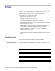
Command Syntax Figure 2-1: Command message elements Commands Commands cause the oscilloscope to perform a specific function or change one of its settings. Commands have the structure: [:][[]...] A command header is made up of one or more mnemonics arranged in a hierarchical or tree structure. The first mnemonic is the base or root of the tree and each subsequent mnemonic is a level or branch off of the previous one.
Command Syntax Clearing the Output Queue To clear the output queue and reset the oscilloscope to accept a new command or query, send a Device Clear (DCL) from a GPIB host. From an RS-232 host, send a break signal. The RS-232 interface responds by returning the ASCII string "DCL." From a USB host, send an INITIATE_CLEAR followed by a CHECK_CLEAR_STATUS. The USB interface responds to CHECK_CLEAR_STATUS with STATUS_SUCCESS when it is finished clearing the output queue.
Command Syntax ACQuire:MODe AVErage; NUMAVg 16 The longer version works equally well: ACQuire:MODe AVErage;:ACQuire:NUMAVg 16 Never precede a star (*) command with a colon or semicolon: ACQuire:MODe AVErage;*TRG The oscilloscope processes commands that follow the star command as if the star command was not there, so: ACQuire:MODe AVErage;*TRG;NUMAVg 16 sets the acquisition mode to average and sets acquisition averaging to 16. The *TRG command is ignored.
Command Syntax GPIB End of Message (EOM) Terminators. GPIB EOM terminators can be the END message (EOI asserted concurrently with the last data byte), the ASCII code for line feed (LF) sent as the last data byte, or both. The oscilloscope always terminates messages with LF and EOI. White space is allowed before the terminator; for example, CR LF is acceptable. USB End of Message (EOM) Terminators.
Command Syntax Waveform Mnemonics Cursor Position Mnemonic Measurement Specifier Mnemonics In some commands you can specify a waveform without regard to its type: channel waveform, math waveform, or reference waveform. The "y" is the same as "x" in Reference Waveform Mnemonics. Symbol Meaning Can be CH, MATH, or REF When the oscilloscope displays cursors, commands may specify which cursor of the pair to use. Symbol Meaning POSITION A cursor selector; is 1 or 2.
Command Syntax Table 2-6: Oscilloscope handling of incorrect numeric arguments Quoted String Arguments Argument value Oscilloscope response Numeric argument is less than lowest correct value for that command Sets the specified command to the lowest correct value and executes the command Numeric argument is greater than the highest correct value for that command Sets the specified command to the highest correct value and executes the command Numeric value is between two correct values Rounds the en
Command Syntax Block Arguments Several oscilloscope commands use a block argument form. Table 2-7: Parts of a block argument Symbol Meaning A nonzero digit character, in the range 1-9 Specifies the number of elements that follow A digit character, in the range 0-9 A character with the hex equivalent of 00 through FF hexadecimal (0 through 255 decimal) A block of data bytes, defined as: := { #[...][...] | #0[...
Command Syntax 2-10 TDS200, TDS1000/2000, TDS1000B/2000B, TDS2000C, TPS2000 Programmer
Command Groups This section lists the commands organized by functional group. The Command Descriptions section lists all commands alphabetically. The oscilloscope GPIB, USB, and RS-232 interfaces conform to Tektronix standard codes and formats except where noted. The GPIB interface also conforms to IEEE Std 488.2–1987 except where noted. The USB interface also conforms to USB Test and Measurement Class, Subclass USB488 Specification, except where noted.
Command Groups Table 2-9: Calibration and Diagnostic commands (cont.) Command Description DIAg:RESUlt:FLAg? Return diagnostic tests status DIAg:RESUlt:LOG? Return diagnostic test sequence results ERRLOG:FIRST? Returns first entry from error log ERRLOG:NEXT? Returns next entry from error log Cursor Commands Cursor commands provide control over the oscilloscope cursor display and readout.
Command Groups Data Logging Commands Data logging commands let you direct the oscilloscope to automatically collect data over a period of time.
Command Groups Table 2-13: File System commands (cont.
Command Groups Table 2-14: Hard Copy commands (cont.
Command Groups Limit Test Commands Limit test commands direct the oscilloscope to monitor an active input signal against a template and to output pass or fail results by judging whether the input signal is within the bounds of the template.
Command Groups Math Commands Math commands provide math function definition.
Command Groups Table 2-18: Measurement commands Command Description MEASUrement? Return all measurement parameters MEASUrement:IMMed? Return immediate measurement parameters MEASUrement:IMMed:SOUrce[1] Set or query the channel for immediate measurement MEASUrement:IMMed:SOURCE2 Set or query the channel for two-source immediate measurements (TPS2000 with Power Analysis Module only) MEASUrement:IMMed:TYPe Set or query the immediate measurement to be taken MEASUrement:IMMed:UNIts? Return the imme
Command Groups Table 2-19: Miscellaneous commands (cont.
Command Groups Table 2-20: PictBridge commands (cont.) Command Description PICTBridge:IMAGESIZE Set or query the image size PICTBridge:PAPERTYPE Set or query the paper type PICTBridge:PRINTQUAL Set or query the print quality PICTBridge:DATEPRINT Set or query the date print PICTBridge:IDPRINT Set or query the ID print Power and Battery-Related Commands (TPS2000 Only) Power and Battery-Related commands provide battery management functions to a TPS2000 oscilloscope.
Command Groups Table 2-22: Power Measurement commands (TPS2000 with TPS2PWR1 only) (cont.) Command Description HARmonics:PERCent? Return the amplitude of the selected harmonic as a percent of the fundamental HARmonics:PHAse? Return the phase of the selected harmonic, in degrees, relative to the fundamental HARmonics:RMS? Return the amplitude of the harmonics source in RMS units.
Command Groups Table 2-22: Power Measurement commands (TPS2000 with TPS2PWR1 only) (cont.
Command Groups Table 2-22: Power Measurement commands (TPS2000 with TPS2PWR1 only) (cont.
Command Groups Table 2-24: Save and Recall commands (cont.) Command Description *SAV Save oscilloscope setting SAVe:IMAge Save screen image to file SAVe:IMAge:FILEFormat Set screen image file format SAVe:SETUp Save oscilloscope setting SAVe:WAVEform Save waveform Status and Error Commands Status and error commands let you determine the status of the oscilloscope and control events. Several commands and queries are common to all devices on the GPIB or USB bus.
Command Groups The three types of triggers are edge, pulse width, and video. Edge triggering is the default type. Edge triggering lets you acquire a waveform when the signal passes through a voltage level of your choosing. Pulse width triggering lets you trigger on normal or aberrant pulses. Video triggering adds the capability of triggering on video fields and lines.
Command Groups Table 2-26: Trigger commands (cont.) Command Description TRIGger:MAIn:VIDeo:STANDard Set or query the video trigger standard (TDS1000, TDS2000, TDS1000B, TDS2000B, TDS2000C, and TPS2000 only) TRIGger:MAIn:VIDeo:SYNC Set or query the video trigger sync TRIGger:STATE? Return trigger system status Vertical Commands Vertical commands control the attributes of the channels. The SELect: command also displays a specified waveform or removes it from the display.
Command Groups min or max of a min/max pair. Before you can transfer waveform data, you must specify the data format and waveform locations. Refer to the text following this table for more information about waveform commands.
Command Groups Table 2-28: Waveform commands (cont.
Command Groups CURVE-110,-109,-110,-110,-109,-107,-109,-107, -106,-105,-103,-100,-97,-90,-84,-80 Binary data can be represented by signed integer or positive integer values. The range of the values depends on the byte width specified.
Command Groups NOTE. The oscilloscope stores waveforms that are ≤2500 data points long. The oscilloscope truncates waveforms longer than 2500 data points. Waveform Preamble Each waveform that is transferred has an associated waveform preamble that contains information such as the horizontal scale, vertical scale, and other settings in place when the waveform was created. Refer to the WFMPre? commands for more information about the waveform preamble.
Command Descriptions Commands either set or query oscilloscope values. Some commands both set and query, some only set, and some only query.
Command Descriptions ACQuire:MODe Sets or queries the oscilloscope acquisition mode. This affects all live waveforms and is equivalent to setting the Mode option in the Acquire menu. Waveforms are the displayed data point values taken from acquisition intervals. Each acquisition interval represents a time duration that is determined by the horizontal scale (time per division). The oscilloscope sampling system can operate at a rate greater than that indicated by the horizontal scale.
Command Descriptions ACQuire:NUMACq? (Query Only) Indicates the number of acquisitions that have taken place since starting oscilloscope acquisition. The maximum number of acquisitions that can be counted is 231-1. This value is reset to zero when you change most Acquisition, Horizontal, Vertical, or Trigger arguments that affect the waveform except for the following: Changing the trigger level or trigger holdoff when in Sample or Peak Detect mode does not reset the value NOTE.
Command Descriptions Arguments Examples is the number of waveform acquisitions. Correct values are 4, 16, 64, and 128. ACQUIRE:NUMAVG 16 specifies that an averaged waveform will show the result of combining 16 separately acquired waveforms. ACQUIRE:NUMAVG? might return 64, indicating that there are 64 acquisitions specified for averaging. ACQuire:STATE Starts or stops oscilloscope acquisitions. This command is the equivalent of pressing the front-panel RUN/STOP button.
Command Descriptions Group Acquisition Syntax ACQuire:STOPAfter { RUNSTop | SEQuence} ACQuire:STOPAfter? Arguments RUNSTop specifies that the run and stop states should be determined by pressing the front-panel RUN/STOP button or issuing the ACQuire:STATE command. SEQuence specifies "single sequence" operation, where the oscilloscope stops after it has acquired enough waveforms to satisfy the conditions of the acquisition mode.
Command Descriptions is the command that caused the error and may be returned when a command error is detected by the oscilloscope. As much of the command is returned as possible without exceeding the 60 character limit of the and strings combined. The command string is right-justified.
Command Descriptions Arguments OFF deactivates the Autorange feature. ON activates the Autorange feature. = 0 deactivates the Autorange feature. ≠ 0 activates the Autorange feature. Examples AUTORANGE:STATE ON starts the Autorange function. AUTORANGE:STATE? returns 0 or 1, depending on whether the Autorange function is on. AUTORange:SETTings Controls the parameters that the Autorange function can adjust. It is equivalent to the option buttons in the Autorange menu.
Command Descriptions For a detailed description of the Autoset function, refer to the user manual for your oscilloscope. Group Miscellaneous Syntax AUTOSet EXECute Arguments EXECute invokes Autoset. AUTOSet:ENABLE Allows educators to disable or enable the Autorange and Autoset functions. The function can be manually set from the Service Diag menu. To access the menu, refer to the TDS1000B and TDS2000B Series or to the TDS2000C Series service manual.
Command Descriptions NONE if the AUTOSET menu is not displayed. AUTOSet:VIEW (No Query Form) If the current menu is not the Autoset menu, or if the view is not valid for the detected waveform, the set command causes the oscilloscope to generate error 221 (Settings conflict). Conditions This command applies to the TDS1000, TDS2000, TDS1000B, TDS2000B, TDS2000C, and TPS2000 Series only.
Command Descriptions Examples AUTOSET:VIEW EVEN will display video signals synchronized on even fields when operated in autoset mode. BUSY? (Query Only) Returns the status of the oscilloscope. This command allows you to synchronize the operation of the oscilloscope with your application program. (See page 3-7, Synchronization Methods.) Certain oscilloscope operations can affect the BUSY? response. (See Table 3-3 on page 3-7.
Command Descriptions Syntax Related Commands Returns *CAL? CALibrate:INTERNAL 0 indicates that the self-calibration completed without any errors detected. Any value other than zero indicates that the self-calibration did not complete successfully or completed with errors. Examples *CAL? performs a self-calibration and might return 0 to indicate that it completed successfully. CALibrate:ABOrt (No Query Form) NOTE. You should only use this command in a qualified service environment.
Command Descriptions Syntax Examples CALibrate:CONTINUE CALIBRATE:CONTINUEperforms the next step in the factory calibration operation. CALibrate:FACtory (No Query Form) NOTE. You should only use this command in a qualified service environment. For more information about the factory calibration sequence, refer to the service manual for your oscilloscope. Starts the oscilloscope internal factory calibration operation. The calibration operation consists of a sequence of steps.
Command Descriptions Syntax Related Commands Examples CALibrate:INTERNAL *CAL? CALIBRATE:INTERNALperforms an internal self-calibration. CALibrate:STATUS? (Query Only) Returns the status of the last calibration operation performed (either self- or factory-calibration) since power on. Group Calibration and Diagnostic Syntax CALibrate:STATUS? Returns PASS indicates that the oscilloscope completed the last calibration operation without detecting any errors.
Command Descriptions Returns Examples Oscilloscope vertical settings. CH1? might return the following string for channel 1: CH1:SCALE 1.0E0;POSITION 0.0E0; COUPLING DC;BANDWIDTH OFF;PROBE 1.0E0 CH:BANdwidth Sets or queries the bandwidth setting of the specified oscilloscope channel. The value of can vary from 1 through 4 for 4-channel instruments or 1 through 2 for 2-channel instruments. This command is equivalent to setting the BW Limit option in the Vertical menu.
Command Descriptions This command is equivalent to setting the Coupling option in the Vertical menu. Group Vertical Syntax CH:COUPling { AC | DC | GND } CH:COUPling? Arguments AC sets the specified oscilloscope channel to AC coupling. DC sets the specified oscilloscope channel to DC coupling. GND sets the specified oscilloscope channel to ground. Only a flat ground-level waveform is displayed. Examples CH1:COUPLING AC establishes AC coupling on channel 1. CH2:COUPLING? might return DC.
Command Descriptions 10 sets the specified oscilloscope channel to 10X attenuation. 50 sets the specified oscilloscope channel to 50X attenuation. 100 sets the specified oscilloscope channel to 100X attenuation. 1000 sets the specified oscilloscope channel to 1000X attenuation. Returns Examples CH2:CURRENTPROBE 1000 sets channel 2 to 1000X attenuation. CH1:CURRENTPROBE? might return 10. CH:INVert NOTE. You cannot use this command with a TDS210 or TDS220 oscilloscope with firmware below V 2.
Command Descriptions CH:POSition Sets or queries the vertical position of the specified oscilloscope channel. The value of can vary from 1 through 4 for 4-channel instruments or 1 through 2 for 2-channel instruments. The position voltage value is applied to the signal before digitization. This command is equivalent to adjusting the front-panel VERTICAL POSITION knob.
Command Descriptions Group Vertical Syntax CH:PRObe { 1 | 10 | 20 | 50 | 100 | 500 | 1000 } CH:PRObe? Arguments 1 sets the specified oscilloscope channel to 1X attenuation. 10 sets the specified oscilloscope channel to 10X attenuation. 20 sets the specified oscilloscope channel to 20X attenuation. (TDS1000B, TDS2000B, TDS2000C, and TPS2000 Series only) 50 sets the specified oscilloscope channel to 50X attenuation.
Command Descriptions Arguments Examples is the gain, in volts or amps per division. For example, the voltage range is 5 V/div to 2 mV/div when using a 1X voltage probe. CH1:SCALE 100E-3 sets the channel 1 gain to 100 mV/div. CH2:SCALE? might return 1.0E0 , indicating that the current V/div setting of channel 2 is 1 V/div. CH:VOLts Sets or queries the vertical gain of the specified channel.
Command Descriptions *CLS (No Query Form) The *CLS command clears the following oscilloscope status data structures: The Event Queue The Standard Event Status Register (SESR) The Status Byte Register (except the MAV bit) If the *CLS command immediately follows an , the Output Queue and MAV bit (Status Byte Register bit 4) are also cleared. MAV indicates information is in the output queue.
Command Descriptions CURSor:FUNCtion Selects and displays the oscilloscope cursor type. Cursors are attached to the waveform selected by CURSor:SELect:SOUrce. This command is equivalent to setting the Type option in the Cursor menu. Setting the function to anything other than OFF causes the Cursor menu to be displayed. NOTE. Setting the display format to XY removes the cursors.
Command Descriptions CURSor:HBArs:DELTa? (Query Only) Returns the difference (in vertical units) between the two horizontal bar cursors in the oscilloscope display. NOTE. If Trigger View is active, this query returns 9.9E37 and generates event 221 (Settings conflict). Group Cursor Syntax CURSor:HBArs:DELTa? Returns Examples CURSOR:HBARS:DELTA? might return 5.08E0 for the difference between the two cursors. CURSor:HBArs:POSITION Positions a horizontal bar cursor.
Command Descriptions Examples CURSOR:HBARS:POSITION1 25.0E-3 positions one of the horizontal cursors at 25.0 mV (assuming the vertical units are volts). CURSOR:HBARS:POSITION2 might return -6.40E-2, indicating that the second horizontal bar cursor is at -64.0 mV (assuming the vertical units are volts). CURSor:HBArs:UNIts? (Query Only) Returns the vertical scale units for the selected cursor source waveform.
Command Descriptions CURSor:SELect:SOUrce Sets or queries the waveform that is the source of the vertical and horizontal scale factors used in determining cursor values. This command is equivalent to setting the Source option in the Cursor menu. Group Cursor Syntax CURSor:SELect:SOUrce CURSor:SELect:SOUrce? Arguments Examples specifies the waveform data source on which cursor measurements will be taken. CURSOR:SELECT:SOURCE CH1 selects channel 1. CURSOR:SELECT:SOURCE? might return MATH.
Command Descriptions Group Cursor Syntax CURSor:VBArs:DELTa? Returns Examples CURSOR:VBARS:DELTA? might return 8.92E-1, indicating that the time difference between the vertical bar cursors is 0.892 seconds. CURSor:VBArs:HDELTa? (Query Only) Returns the time or frequency difference between the two vertical bar cursors. The units (seconds or Hertz) are specified by the CURSor:VBArs:UNIts command.
Command Descriptions Conditions This command applies to the TDS1000B, TDS2000B, TDS2000C, and TPS2000 Series only. Group Cursor Syntax CURSor:VBArs:HPOS? Related Commands Returns Examples CURSor:HBArs:UNIts? indicates the amplitude value at the selected position. CURSOR:VBARS:HPOS1? might return 1.37, indicating the value of one vertical bar tic. CURSor:VBArs:POSITION Positions a vertical bar cursor.
Command Descriptions CURSOR:VBARS:POSITION1? might return 1.00E-6, indicating the first vertical bar cursor is at 1 μs. CURSor:VBArs:SLOPE? (Query Only) Returns the change in amplitude divided by the change in time, as measured between the two cursors. The units are derivable from the CURSor:HBArs:UNIts and CURSor:VBArs:UNIts queries. Conditions This command applies to the TPS2000 Series with TPS2PWR1 Power Analysis Module only.
Command Descriptions CURSor:VBArs:VDELTa? (Query Only) Returns the vertical (amplitude) difference between the two vertical bar cursors. The units are specified by the CURSor:HBArs:UNits query. Conditions This command applies to the TDS1000B, TDS2000B, TDS2000C, and TPS2000 Series only. Group Cursor Syntax CURSor:VBArs:VDELTa? Returns Examples indicates the vertical difference between the two vertical bar cursors. CURSOR:VBARS:VDELTA? might return 1.
Command Descriptions Refer to Waveform Commands for a description of the waveform transfer process. (See page 2-26.) Group Waveform Syntax CURVe { | } CURVe? Related Commands Arguments DATa, is the waveform data in binary format. The waveform is formatted as: # where is the number of characters in . For example, if = 500, then = 3, where is the number of bytes to transfer.
Command Descriptions Examples DATA INIT reinitializes the waveform data settings to their factory defaults: DESTINATION = REFA (=TARGET) ENCDG = RIBINARY SOUrce = CH1 START = 1 STOP = 2500 WIDTH = 1 DATA? might return the following string: DATA:ENCDG RPBINARY;DESTINATION REFA; SOURCE REFB;START 1;STOP 500;WIDTH 2 DATa:DESTination Sets or queries the reference memory location for storing oscilloscope waveform data that is transferred into the oscilloscope by the CURVe command.
Command Descriptions Syntax Related Commands Arguments DATa:ENCdg { ASCIi | RIBinary | RPBinary | SRIbinary | SRPbinary } DATa:ENCdg? WFMPre:ENCdg, WFMPre:BN_Fmt, ASCIi specifies the ASCII representation of signed integer (RIBinary) data. If this is the value at power-on, the WFMPre values for BN_Fmt, BYT_Or, and ENCdg are set as RP, MSB, and ASC respectively. RIBinary specifies signed integer data-point representation with the most significant byte transferred first.
Command Descriptions DATa:SOUrce Sets or queries which waveform will be transferred from the oscilloscope by the CURVe, WFMPre, or WAVFrm? queries. You can transfer only one waveform at a time. Group Waveform Syntax DATa:SOUrce DATa:SOUrce? Related Commands Arguments Examples CURVe, WFMPre?, is the location of the waveform data that will be transferred from the oscilloscope to the external device. Allowable values are CH, MATH, and REF.
Command Descriptions Examples DATA:START 10 specifies that the waveform transfer will begin with data point 10. DATA:START? might return 214 as the first waveform data point that will be transferred. DATa:STOP Sets or queries the last data point in the waveform that will be transferred when executing the CURVe? command. This lets you transfer partial waveforms from the oscilloscope.
Command Descriptions DATa:WIDth Sets the number of bytes per waveform data point to be transferred when executing the CURVe command. (Changing DATa:WIDth may change the following WFMPre parameters: BIT_Nr, BYT_Nr, YMULt, YOFf, and YZEro.) Group Waveform Syntax DATa:WIDth DATa:WIDth? Related Commands Arguments CURVe, WFMPre:BIT_Nr, = 1 sets the number of bytes per waveform data point to 1 byte (8 bits). = 2 sets the number of bytes per waveform data point to 2 bytes (16 bits).
Command Descriptions Arguments Examples { 30 | 60 | 90 | 120 | 150 | 180 | 210 | 240 | 270 | 300 | 330 | 360 | 390 | 420 | 450 | 480 } is the data logging time period, in minutes. DATALOGGING:DURATION 30 enables data logging to last for 30 minutes. DATALOGging:SOURCE Sets up the data logging source. Group Data Logging Syntax DATALOGging:SOURCE { CH | MATH } Related Commands Arguments DATALOGging:DURAtion, DATALOGging:STATE CH is a channel, where is 1, 2, 3, or 4.
Command Descriptions Examples DATALOGGING:STATE ON turns on data logging. DATE Sets or queries the oscilloscope date value. The oscilloscope uses these values to time stamp files saved to the CompactFlash card (TDS2MEM and TPS2000 Series only), or to the USB flash drive (TDS1000B, TDS2000B and TDS2000C Series only), as well as show the time and date on the oscilloscope display. Conditions This command applies to the TDS2MEM, TDS1000B, TDS2000B, TDS2000C, and TPS2000 Series only.
Command Descriptions Arguments or is a complete sequence of program messages. The messages must contain only valid commands that must be separated by semicolons and must follow all rules for concatenating commands (See page 2-4, Concatenating Commands.). The sequence must be ≤80 characters. format is always returned as a query response. Examples *DDT #217ACQuire:STATE RUN specifies that the acquisition system will be started each time a *TRG command is sent.
Command Descriptions DIAg:RESUlt:FLAg? (Query Only) Returns the Pass/Fail status from the last diagnostic test sequence execution (those run automatically at power on, or those requested through the Service Menu). Use the DIAg:RESUlt:LOG? query to determine which test(s) has failed. Group Calibration and Diagnostic Syntax DIAg:RESUlt:FLAg? Returns PASS means that the oscilloscope passes all diagnostic tests. FAIL means that the oscilloscope has failed at least one of the diagnostic tests.
Command Descriptions Group Display Syntax DISplay? Returns Examples The current display settings DISPLAY? might return DISPLAY:FORMAT YT;STYLE VECTORS; PERSISTENCE OFF;CONTRAST 50; INVERT OFF. DISplay:BRIGHTness Sets or queries the brightness of the LCD display. Conditions This command applies to the TPS2000 Series only.
Command Descriptions Related Commands Arguments Examples DISplay:INVert, is an integer in the range from 1 through 100. The larger the value, the greater the screen contrast. DISPLAY:CONTRAST 63 sets the display contrast to 63%. DISplay:FORMat Sets or queries the oscilloscope display format. This command is equivalent to setting the Format option in the Display menu.
Command Descriptions The TDS200 Series is not supported. Group Display Syntax DISplay:INVert { ON | OFF} DISplay:INVert? Arguments OFF chooses a default black-on-white display. ON chooses a white-on-black display. Examples DISPLAY:INVERT might return OFF. DISplay:PERSistence Sets the length of time that data points are displayed.
Command Descriptions DISplay:STYle Selects how to display the waveform data. This command is equivalent to setting the Type option in the Display menu. Group Display Syntax DISplay:STYle { DOTs | VECtors } DISplay:STYle? Arguments DOTs displays individual data points. VECtors connects adjacent data points. Examples DISPLAY:STYLE VEC sets the display to connect adjacent data points. DISPLAY:STYLE might return DOTS indicating that the display shows individual waveform data points.
Command Descriptions Syntax Returns ERRLOG:NEXT? Refer to the service manual for your oscilloscope for information about error log message format. *ESE (No Query Form) Sets and queries the bits in the Event Status Enable Register (ESER). The ESER prevents events from being reported to the Status Byte Register (STB). (See page 3-1, Status and Events.
Command Descriptions Group Status and Error Syntax *ESR? Related Commands Returns Examples ALLEv?, *CLS, DESE, *ESE, EVENT?, EVMsg?, *OPC, *SRE, Contents of the Standard Event Status Register. *ESR? might return the value 213, showing that the SESR contains binary 11010101. EVENT? (Query Only) Returns from the Event Queue an event code that provides information about the results of the last *ESR? read. EVENT? also removes the returned value from the Event Queue.
Command Descriptions Related Commands Returns ALLEv?, *CLS, DESE, *ESE, *ESR?, EVENT?, *SRE, The event code and message in the following format: [ ...] ::= ;[] where is the command that caused the error and may be returned when a command error is detected by the oscilloscope. As much of the command as possible is returned without exceeding the 60 character limit of the and strings combined.
Command Descriptions Syntax FACtory Setting the oscilloscope to factory default has the following impact on the programming interface: Clears the Event Status Enable Register Clears the Service Request Enable Register Sets the Device Event Status Enable Register to 255 Sets the Power On Status Clear Flag to TRUE Enables all Command Headers (HEADer ON) Sets the macro defined by *DDT to a "zero-length field" Clears the pending operation flag and associated operations Performs the equivalent of DATA INIT Th
Command Descriptions FILESystem? (Query Only) Returns the current working directory and amount of free space on the CompactFlash card (TDS2MEM and TPS2000 Series only), or on the USB flash drive (TDS1000B, TDS2000B, and TDS2000C Series only). Group File system Syntax FILESystem? Related Commands Examples FILESYSTEM? might return FILESYSTEM:CWD "A:\";FREESPACE 29691904.
Command Descriptions FILESystem:DELEte (No Query Form) Deletes the specified file name from the CompactFlash card (TDS2MEM and TPS2000 Series only), or from the USB flash drive (TDS1000B, TDS2000B, and TDS2000C Series only). Conditions This command applies to the TDS2MEM, TDS1000B, TDS2000B, TDS2000C, and TPS2000 Series only.
Command Descriptions FILESystem:FORMat (No Query Form) Formats the CompactFlash card (TDS2MEM and TPS2000 Series only) or the USB flash drive (TDS1000B, TDS2000B, and TDS2000C Series only). Formatting a CompactFlash card or a USB flash drive deletes all files and folders on the memory device. Conditions This command applies to the TDS2MEM, TDS1000B, TDS2000B, TDS2000C, and TPS2000 Series only.
Command Descriptions FILESystem:MKDir (No Query Form) Creates a folder at the specified location on the CompactFlash card (TDS2MEM and TPS2000 Series only), or on the USB flash drive (TDS1000B, TDS2000B, and TDS2000C Series only). Conditions This command applies to the TDS2MEM, TDS1000B, TDS2000B, TDS2000C and TPS2000 Series only. Group File system Syntax FILESystem:MKDir Arguments is a quoted string that defines the location and name of the folder to create.
Command Descriptions Arguments is a quoted string that defines the path and name of the file to rename. If you do not specify a path to the file, the oscilloscope looks for the file in the current working folder. The current directory refers to the name of a folder as returned by the FILESystem:CWD query. is a quoted string that defines the path and new name of the file.
Command Descriptions HARDCopy Sends a copy of the screen display followed by an EOI to the port specified by HARDCopy:PORT. The format and layout of the output is specified with the HARDCopy:FORMat and HARDCopy:LAYout commands. This command is equivalent to pressing the PRINT button on the front panel of the TDS1000, TDS2000, TDS1000B, TDS2000B, TDS2000C, and TPS2000 Series or the HARDCOPY button on the front panel of the TDS200 Series. NOTE.
Command Descriptions HARDCopy:BUTTON Sets or returns the current PRINT front-panel button function. NOTE. This command does not affect the HARDCopy STARt command. Conditions This command applies to the TDS2MEM, TDS1000B, TDS2000B, TDS2000C, and TPS2000 Series only. Group Hard copy Syntax HARDCopy:BUTTON { PRINTS | SAVESAll | SAVESImage } HARDCopy:BUTTON? Arguments PRINTS sets the PRINT button to send the screen image to the current printer port, using the current printer format.
Command Descriptions NOTE. The TDS1000B, TDS2000B, and TDS2000C oscilloscopes provide PictBridge printer support through a USB Device port on the rear of the oscilloscope. (See page 2-19, PictBridge Commands (TDS2000C, TDS1000B and TDS2000B Only).) The HARDCopy:FORMat is always Exif/JPEG when printing to a PictBridge printer. For TDS1000B, TDS2000B, and TDS2000C oscilloscopes, use the HARDCopy:FORMat command to set the file format when saving an image to a USB flash drive or over USBTMC.
Command Descriptions JPEG (TDS1000B, TDS2000B, and TDS2000C Series only) sets the hard copy format to JPEG format. LASERJet (TDS200, TDS1000, TDS2000, and TPS2000 Series only) sets the hard copy output format to HP LaserJet II printer format. PCX sets the hard copy output format to DOS Paintbrush format. RLE (TDS1000, TDS2000, TDS1000B, TDS2000B, TDS2000C and TPS2000 Series only) sets the hard copy output format to Windows color image file format (*.RLE).
Command Descriptions Examples HARDCOPY:INKSAVER? might return ON. HARDCopy:LAYout Selects the printing orientation. This command is equivalent to setting the Layout option in the UTILITY > Options > Hard Copy Setup menu. NOTE. This command also controls the format of saved images. Only TDS1000B, TDS2000B, and TDS2000C oscilloscopes are compatible with PictBridge printers. When printing to a PictBridge printer, the printer determines the orienatation and will override the argument.
Command Descriptions Syntax Arguments HARDCopy:PORT { CENtronics | RS232 | GPIb | USB } HARDCopy:PORT? CENtronics specifies that the hard copy data is sent out the Centronics port. RS232 specifies that the hard copy data is sent out the RS232 port. If you set the port to RS232, and use it to transfer a BMP screen image format file to a PC or other computer, observe the following precaution that the BMP file is a binary file, and therefore does not use linefeeds (hexadecimal 0a) as a terminator.
Command Descriptions Conditions This command applies to the TPS2000 Series with TPS2PWR1 Power Analysis Module only. Group Power Measurement Syntax HARmonics:ENABle { ON | OFF } HARmonics:ENABle? Arguments ON causes the oscilloscope to display the harmonics menu and turn on Harmonics analysis. OFF causes the oscilloscope to display the CH1 menu. Examples HARMONICS:ENABLE ON causes the oscilloscope to display the harmonics menu.
Command Descriptions Returns Examples HARMONICS:HRMS? might return 6.18267221409E-1. HARmonics:PERCent? (Query Only) Returns the amplitude of the selected harmonic as a percent of the fundamental. Group Power Measurement Syntax HARmonics:PERCent? Related Commands Examples HARMONICS:PERCENT? might return 5.0, indicating that the amplitude of the selected harmonic as a percent of the fundamental frequency is 5.0%.
Command Descriptions Examples HARMONICS:RMS? might return 120.0, indicating that the RMS value is 120 volts RMS. HARmonics:SAVe (No Query Form) Sets the file name and path to save the selected waveform harmonic data to the oscilloscope CompactFlash card in .CSV format. The following data is included in the file: Harmonics, 1 through 50 Magnitude Percent of fundamental Frequency Phase angle NOTE. You can view the contents of the saved file on your personal computer.
Command Descriptions Conditions This command applies to the TPS2000 Series with TPS2PWR1 Power Analysis Module only. Group Power Measurement Syntax HARmonics:SELect HARmonics:SELect? Related Commands Arguments Examples specifies the harmonic from 1 to 50. HARMONICS:SELECT 1 instructs the oscilloscope to select the first harmonic. HARMONICS:SELECT? might return 3, indicating that the third harmonic is selected.
Command Descriptions HARmonics:SHOW Sets or returns the type of displayed harmonics. Conditions This command applies to the TPS2000 Series with TPS2PWR1 Power Analysis Module only. Group Power Measurement Syntax HARmonics:SHOW { ALL | ODD | EVEN } HARmonics:SHOW? Arguments ALL displays both odd and even harmonics. ODD displays odd harmonics only. EVEN displays even harmonics only. Examples HARMONICS:SHOW ALL instructs the oscilloscope to display all harmonics.
Command Descriptions Examples HARMONICS:SOURCE CH1 sets the source for the harmonics function to CH1. HARMONICS:SOURCE might return CH1, indicating that the harmonics source is channel 1. HARmonics:THDF? (Query Only) Returns total harmonic distortion of the waveform as a percentage of the fundamental. Group Power Measurement Syntax HARmonics:THDF? Returns Examples HARMONICS:THDF? might return 1.1117748204298E1, indicating that the total harmonic distortion is 11.
Command Descriptions Group Miscellaneous Syntax HDR HEADer Sets and queries the Response Header Enable State that causes the oscilloscope to either include or omit headers on query responses. This command does not affect IEEE Std 488.2-1987 Common Commands (those starting with an asterisk); they never return headers. Group Miscellaneous Syntax HEADer { | OFF | ON } HEADer? Related Commands Arguments ON or ≠ 0 sets the Response Header Enable State to true.
Command Descriptions Syntax Returns Examples HORizontal? Returns all horizontal settings HORIZONTAL? might return the following string: HORIZONTAL:VIEW MAIN;RECORDLENGTH 2500;MAIN:POSITION 0.0E0;SCALE 5.0E-4;HORIZONTAL:DELAY:POSITION 0.0E0;SCALE 2.5E-4 HORizontal:DELay? (Query Only) Returns all settings for the window time base. The commands HORizontal:DELay:SECdiv and HORizontal:DELay:SCAle are equivalent, so only the values for HORizontal:DELay:SCAle are returned.
Command Descriptions Examples HORIZONTAL:DELAY:POSITION 2.0E-6 sets the window position to 2ms before the center graticule. HORIZONTAL:DELAY:POSITION? might return -1.0E-3, indicating that the window position is 1 ms after the center graticule. HORizontal:DELay:SCAle Sets the time per division for the oscilloscope window time base. This command is equivalent to setting SEC/DIV when Window Zone or Window is selected from the Horizontal menu.
Command Descriptions HORizontal:MAIn? (Query Only) Returns all settings for the oscilloscope main time base. The HORizontal:MAIn:SECdiv and HORizontal:MAIn:SCAle commands are identical so only HORizontal:MAIn:SCAle is returned. Group Horizontal Syntax HORizontal:MAIn? Returns Examples All settings for the main time base. HORIZONTAL:MAIN? might return HORIZONTAL:MAIN:POSITION 0.0E0;SCALE 5.0E-4 HORizontal:MAIn:POSition Sets or queries the main time base horizontal position.
Command Descriptions HORizontal:MAIn:SCAle Sets the time per division for the main time base. This command is equivalent to setting SEC/DIV when Main is selected from the Horizontal menu. Group Horizontal Syntax HORizontal:MAIn:SCAle HORizontal:MAIn:SCAle? Arguments is the time per division. The range depends on the oscilloscope model. The acceptable values are in a 1-2.5-5 sequence. Other values are forced to the closest acceptable value. Examples HORIZONTAL:MAIN:SCALE 2.
Command Descriptions Arguments is the position in seconds. This value is the difference between the trigger point and the center graticule. Positive values place the trigger before the center graticule. Examples HORIZONTAL:POSITION 2.0E-6 sets the main trigger position to 2ms before the center graticule. HORIZONTAL:POSITION? might return -1.0E-3, indicating that the main trigger position is 1 ms after the center graticule.
Command Descriptions HORizontal:SECdiv Sets the time per division for the main time base and is identical to the HORizontal:MAIn:SCAle command. It is included for compatibility purposes. Group Horizontal Syntax HORizontal:SECdiv HORizontal:VIEW Specifies whether the horizontal display uses the Main, Window Zone, or Window view. This is equivalent to setting the View in the Horizontal menu.
Command Descriptions Group Miscellaneous Syntax ID? Returns Returns the oscilloscope identification in the following format for TDS2CM, TDS2CMA, and TDS2MM modules: ID TEK/,CF:91.1CT,FV:v,TDS2XX:XXV:v Where XX is the module type, CM (TDS2CM or TDS2CMA communications module) or MM (measurement module). Returns the oscilloscope identification in the following format for TDS2MEM modules: ID TEK/,CF:91.
Command Descriptions NOTE. *IDN? must be the last command when part of a concatenated statement. Otherwise the oscilloscope generates event message 440. The *IDN? and ID? responses are slightly different. Group Miscellaneous Syntax *IDN? Related Commands Returns Returns the oscilloscope identification in the following format for TDS2CM, TDS2CMA, and TDS2MM modules: TEKTRONIX, ,CF:91.
Command Descriptions *IDN? might return the following response for a TPS2022B oscilloscope with the serial number CU10100: TEKTRONIX,TDS 2022B,CU10100,CF:91.1CT FV:v20.22 *IDN? might return the following response for a TDS1012B oscilloscope with the serial number CU010114: TEKTRONIX,TDS 1012B,CU010114,CF:91.1CT FV:v21.21 LANGuage Sets or queries the languages that the oscilloscope uses to display information on the screen. This is equivalent to setting the Language option in the Utility menu.
Command Descriptions LIMit:COMpare Sets or returns the template against which to compare the waveform acquired through the specified channel. The template can be a waveform saved in any of the reference locations REF1 through REF4. Group Limit Test Syntax LIMit:COMpare :REF LIMit:COMpare? Related Commands Arguments Examples LIMit:TEMPLate REF is a reference waveform, where is 1, 2, 3, or 4.
Command Descriptions LIMit:RESUlt:PASS? (Query Only) Returns the number of pass cases. Group Limit Test Syntax LIMit:RESUlt:PASS? Related Commands Examples LIMit:RESUlt:FAIL?, LIMit:RESUlt:TOTAL? LIMIT:RESULT:PASS? might return: 25, indicating that 25 test cases were detected as passing. LIMit:RESUlt:TOTAL? (Query Only) Returns the number of total cases tested.
Command Descriptions Related Commands Arguments LIMit:SAVEWFM OFF or = 0 turns off the function to save waveform image data to the flash drive for limit testing. ON or ≠ 0 turns on the function to save waveform image data to the flash drive for limit testing. Examples LIMIT:SAVEIMAGE ON turns on the function to save waveform image data to the flash drive for limit testing.
Command Descriptions Group Limit Test Syntax LIMit:SOUrce { CH | MATH } LIMit:SOUrce? Related Commands Arguments LIMit:TEMPLate:SOUrce CH specifies that the source channel for the waveform currently being compared to the test template. MATH specifies the source channel as the math waveform. Examples LIMIT:SOURCE MATH sets the MATH waveform as the source channel. LIMit:STATE Turns limit testing on or off, or returns whether limit testing is in effect.
Command Descriptions Syntax Related Commands Arguments LIMit:STOPAfter:MODe { MANual | WAVEform | VIOLation | TIMe } LIMit:STOPAfter:MODe? LIMit:STOPAfter:TIMe, LIMit:STOPAfter:VIOLation, LIMit:STOPAfter: WAVEform MANual causes the test to stop after an operator manually stops it. WAVEform causes the test to stop after the oscilloscope tests a specified number of waveforms. VIOLation causes the test to stop after the oscilloscope detects a violation.
Command Descriptions LIMit:STOPAfter:VIOLation Sets or returns the limit test stop after violation setting. The test will automatically stop after it detects the specified number of violations. Group Limit Test Syntax LIMit:STOPAfter:VIOLation LIMit:STOPAfter:VIOLation? Related Commands Arguments Examples LIMit:STOPAfter:MODe, LIMit:STOPAfter:TIMe, LIMit:STOPAfter:WAVEform is the number of violations to detect before stopping the limit test.
Command Descriptions LIMit:TEMPLate:TOLerance:VERTical to create a limit test template and store the template in the reference waveform memory location specified in LIMit:TEMPLate:DESTination. You can compare the waveform acquired through the specified channel against this template. The template can be a waveform saved in any of the reference locations REF1 through REF4.
Command Descriptions Examples LIMIT:TEMPLATE:DESTINATION REF2 specifies that the template waveform referred to with the LIMit:TEMPLate APPLY command is stored as the REF2 waveform. LIMit:TEMPLate:SOUrce Sets or returns the source channel or math waveform that LIMit:TEMPLate APPLY will use in deriving the limit test template waveform.
Command Descriptions Related Commands Arguments Examples LIMit:TEMPLate, LIMit:TEMPLate:DESTination, LIMit:TEMPLate:SOUrce, LIMit:TEMPLate:TOLerance:VERTical is the amount, in horizontal divisions, by which the source waveform is horizontally modified to generate the template that is stored in the destination reference. The range is 0 to 5 divisions. LIMIT:TEMPLATE:TOLERANCE:HORIZONTAL 1.0 specifies that the source waveform is modified horizontally by a ±1.
Command Descriptions Group Miscellaneous Syntax LOCk { ALL | NONe } LOCk? Arguments ALL disables all front-panel controls. NONe enables all front-panel controls. This is equivalent to the UNLock ALL command. Examples LOCK ALL locks the front-panel controls. LOCK? returns NONE when the front-panel controls are enabled by this command. *LRN? (Query Only) This is identical to the SET? query.
Command Descriptions MATH:DEFINE Performs the specified mathematical operation on the input signal or signals. To activate or deactivate the math waveform, use the SELect: command. NOTE. Remember that must be enclosed in quotes. You can use white space characters between words.
Command Descriptions MATH:DEFINE "FFT (CH1, HANNING)" sets the math waveform to display an FFT of channel 1 using a Hanning window. NOTE. You can use this example with TDS1000, TDS2000, TDS1000B, TDS2000B, TDS2000C, and TPS2000 Series oscilloscopes, as well as a TDS200 Series oscilloscope with a TDS2MM measurement module. MATH:FFT? (Query Only) NOTE.
Command Descriptions Arguments specifies the point in the FFT waveform data record to display at the Examples MATH:FFT:HORIZONTAL:POSITION 25 sets the FFT waveform horizontal center vertical graticule line. The data record point is a percentage of the total record length, in the range of 0 to 100. The default value is 50. How much data is displayed depends on the FFT Zoom factor setting. The oscilloscope rounds to the nearest workable value.
Command Descriptions MATH:FFT:VERtical:POSition NOTE. You can use this command with TDS1000, TDS2000, TDS1000B, TDS2000B, TDS2000C, and TPS2000 oscilloscopes, as well as a TDS200 oscilloscope with a TDS2MM measurement module. Sets or queries the FFT math waveform vertical position. Group Math Syntax MATH:FFT:VERtical:POSition MATH:FFT:VERtical:POSition? Arguments Examples specifies the FFT waveform vertical position in divisions.
Command Descriptions other values are entered the oscilloscope rounds the value of to the nearest valid zoom factor. Examples MATH:FFT:VERTICAL:SCALE 5 sets the FFT waveform vertical zoom factor to X5. MATH:FFT:VERTICAL:SCALE? might return 2.0E0, indicating that the zoom factor setting is X2. MATH:VERtical? (Query Only) Returns the MATH:VERtical display settings. Group Math Syntax MATH:VERtical? Examples MATH:VERTICAL?? might return MATH:VERTICAL:POSITION 0.0E0;SCALE 5.
Command Descriptions MATH:VERtical:SCAle Sets or returns the math waveform display scale in units per division. It is not possible to use this command to set the math scale to a fine scale not achievable from the front panel. This command typically rounds down to an achievable value. If the value input is below the minimum value, then the command will round up. Conditions This command applies to the TDS1000B, TDS2000B, TDS2000C, and TPS2000 Series only.
Command Descriptions MEASUrement:IMMed? (Query Only) Returns all immediate measurement setup parameters. Immediate queries and commands are the preferred methods for programming. An immediate measurement selection is not visible or accessible through the display screen or front panel.
Command Descriptions Conditions This command applies to the TPS2000 Series with TPS2PWR1 Power Analysis Module only. NOTE. This command is only available when the Power Analysis Module application key is installed. Group Measurement Syntax MEASUrement:IMMed:SOURCE2 { CH | MATH } MEASUrement:IMMed:SOURCE2? Arguments CH specifies the measurement source channel as one of the input channels.
Command Descriptions CURSORRms (TDS2000C Series) is the true Root Mean Square (RMS) value of the selected waveform data, between the start point and the end point. DELay (TDS2000C Series) is the delay from one waveform’s edge event to another. FALL (TDS200 Series with a TDS2MM measurement module, TDS1000, TDS2000, TDS1000B, TDS2000B, TDS2000C, and TPS2000 Series only) is the fall time between 90% and 10% of the first falling edge of the waveform. Falling edge must be displayed to measure.
Command Descriptions PFPHASE (TPS2000 Series with TPS2PWR1 Power Analysis Module only) is the phase angle measurement in degrees. Source 1 must be volts; source 2 must be Amperes. PHAse (TPS2000 Series with TPS2PWR1 Power Analysis Module only) is the measurement of phase between source 1 and source 2, in degrees. POWERFACTOR (TPS2000 Series with TPS2PWR1 Power Analysis Module only) is the true power factor ratio measurement. Source 1 must be volts; source 2 must be Amperes.
Command Descriptions For the TDS1000B, TDS2000B, TDS2000C, and TPS2000 Series, can also return the following: A for amps VA for volt-amperes AA for amperes*amperes VV for volts*volts You can also use this command for undefined math waveforms. Examples MEASUREMENT:IMMED:UNITS? might return "s", indicating that the unit for the immediate measurement is seconds. MEASUrement:IMMed:VALue? (Query Only) Executes the immediate oscilloscope measurement specified by the MEASUrement:IMMed:TYPe command.
Command Descriptions Examples MEASUREMENT:IMMED:VALUE? might return 28.75E6 if you are measuring the frequency of a 28.75 MHz signal. MEASUREMENT:IMMED:VALUE? might return 9.9E37, which means that the channel specified by MEASUrement:IMMed:SOUrce is not currently displayed. *ESR? after a measurement query might return 16, indicating that there are error messages in the queue.
Command Descriptions Arguments CH specifies the input channel source for the measurement. MATH specifies the measurement source channel as the math waveform. (TDS1000B, TDS2000B, TDS2000C, and TPS2000 Series only) Examples MEASUREMENT:MEAS2:SOURCE CH1 sets the source for Measurement 2 to channel 1. MEASUrement:MEAS:TYPe Sets or queries the on-screen periodic oscilloscope measurement type for the measurement specified by .
Command Descriptions MAXImum (TDS1000, TDS2000, TDS1000B, TDS2000B, TDS2000C, and TPS2000 Series only) is the value of the largest point in the waveform. MEAN is the arithmetic mean over the entire waveform. MINImum (TDS1000, TDS2000, TDS1000B, TDS2000B, TDS2000C, and TPS2000 Series only) is the value of the smallest point in the waveform. NONE disables the measurement specified by .
Command Descriptions Syntax Returns MEASUrement:MEAS:UNIts? returns "V" for volts, "s" for seconds, or "Hz" for Hertz, or a null string if MEASUrement:MEAS:TYPe is set to NONE. For the TDS1000B, TDS2000B, TDS2000C, and TPS2000 Series, can also return the following: A for amps VA for volt-amperes AA for amperes*amperes VV for volts*volts You can also use this command for undefined math waveforms.
Command Descriptions NOTE. If Trigger View is active, scan mode is in effect, or the display format set to XY, this query generates event 221 (Settings conflict) and returns 9.9E37. NOTE. When math is FFT, turned on, and used as a measurement source, attempting to query the measurement value returns 9.9e37 and raises error 2225 (no waveform to measure). Group Measurement Syntax MEASUrement:MEAS:VALue? Returns Examples MEASUREMENT:MEAS3:VALUE might return 28.
Command Descriptions *OPC? might return 1 to indicate that all pending OPC operations are finished. PICTBridge:DEF (No Query Form) Sets the arguments for all PictBridge commands to their default values. The default values are the same as the default settings for the printer. This command is equivalent to setting all the options to default in the UTILITY > Options > Printer Setup > PRINT Button > Prints menu of TDS1000B, TDS2000B, and TDS2000C oscilloscopes. NOTE.
Command Descriptions Arguments DEFLT specifies the default paper size of the printer. Any paper size argument is valid when the paper is available for the printer. Examples PICTBRIDGE:PAPERSIZE? might return LETTER as the selected paper size for the printer. PICTBridge:IMAGESIZE Sets the size of the image to print. This command is equivalent to setting the Image Size option in the UTILITY > Options > Printer Setup > PRINT Button > Prints menu of TDS1000B, TDS2000B, and TDS2000C oscilloscopes.
Command Descriptions Syntax Arguments Examples PICTBridge:PAPERTYPE { DEFLT | PLAIN | PHOTO | FASTPHOTO} PICTBridge:PAPERTYPE? DEFLT specifies the type of paper used by default in the printer. PICTBRIDGE:PAPERTYPE might return PLAIN as the paper type. PICTBridge:PRINTQUAL Sets the quality of the print from those available on the compatible printer.
Command Descriptions Group PictBridge Syntax PICTBridge:DATEPRINT { DEFLT | OFF | ON } PICTBridge:DATEPRINT? Arguments DEFLT will match the default setting of the printer: on or off. ON prints the date and time on the hard copy. OFF does not print the date and time. Examples PICTBRIDGE:DATEPRINT? might return ON if the printer is set to print the date and time.
Command Descriptions Group Power and Battery-Related Syntax POWer? Examples POWER? might return the following: POWER:AC:PRESENT 1;:POWER:BATTERY1:GASGAUGE 0 ;STATUS NOTINSTALLED;:POWER:BATTERY2:GASGAUGE 0 ;STATUS NOTINSTALLED;:POWER:BATTERIES:TIME 0; POWER:BUTTONLIGHT 1 POWer:AC:PRESENt? (Query Only) Returns a statement indicating whether the oscilloscope is being powered by battery or AC.
Command Descriptions Examples POWER:BATTERY1:GASGAUGE? might return 60, specifying that battery 1 is 60% charged. POWer:BATTERY:STATUS? (Query Only) Returns the status of battery x, where x is Battery 1 or Battery 2. Group Power and Battery-Related Syntax POWer:BATTERY:STATUS? Returns FULL indicates that the battery is fully charged. DISCHARGED indicates that the battery has no charge remaining. The battery can be discharged, but still report a small percent remaining.
Command Descriptions POWer:BUTTONLIGHT Turns the lights on the front-panel buttons of the TPS2000 on and off. Conditions This command applies to the TPS2000 Series only. Group Power and Battery-Related Syntax POWer:BUTTONLIGHT | ON | OFF POWer:BUTTONLIGHT? Arguments ON or ≠ 0 turns the lights on. OFF or = 0 turns the lights off. Examples POWER:BUTTONLIGHT ON sets the front-panel button lights to on. POWerANALYSIS:SOUrces Sets or queries the Power Analysis sources.
Command Descriptions *PSC (No Query Form) Sets and queries the power-on status flag that controls the automatic power-on handling of the DESER, SRER, and ESER registers. When *PSC is true, the DESER register is set to 255 and the SRER and ESER registers are set to 0 at power on. When *PSC is false, the current values in the DESER, SRER, and ESER registers are preserved in nonvolatile memory when power is shut off and are restored at power on. Refer to the Status and Events chapter for more information.
Command Descriptions Arguments is an integer value in the range from 1 to 5 (TDS200 Series), or 1 to 10 Examples *RCL 3 restores the oscilloscope from a copy of the settings stored in memory (TDS1000, TDS2000, TDS1000B, TDS2000B, TDS2000C, and TPS2000 Series), and specifies a setup storage location. location 3.
Command Descriptions RECAll:WAVEForm (No Query Form) Recalls a stored waveform from the CompactFlash card (TDS2MEM and TPS2000 Series only), or from the USB flash drive (TDS1000B, TDS2000B, and TDS2000C Series only) into a reference location. Conditions This command applies to the TDS2MEM, TDS1000B, TDS2000B, TDS2000C, and TPS2000 Series only.
Command Descriptions RS232? (Query Only) Returns the RS232 settings. Group RS-232 Syntax RS232? Returns Examples The current RS-232 settings. RS232? might return the following string: RS232:BAUD 9600; SOFTFLAGGING 0; HARDFLAGGING 1; PARITY NONE; TRANSMIT:TERMINATOR LF RS232:BAUd Sets or queries the RS-232C interface transmission speed. If no flow control (flagging) is used, commands may be received faster than the oscilloscope can process them.
Command Descriptions incoming data until the input buffer is full and then reports an input overrun error. The oscilloscope asserts DTR (Data Terminal Ready) at all times when the oscilloscope power is on. Hard flagging and soft flagging cannot be on at the same time. However, hard and soft flagging can both be off at the same time. Turning hard flagging on turns soft flagging off. Turning soft flagging on turns hard flagging off.
Command Descriptions Arguments EVEN sets even parity. ODD sets odd parity. NONe sets no parity (no ninth bit transmitted). Examples RS232:PARITY EVEN sets even parity. RS232:SOFTFlagging Sets or queries the input and output soft flagging over the RS-232C port. After receiving an XOFF (DC3), the oscilloscope sends two or less characters. The oscilloscope begins transmitting data again when it receives an XON (DC1) character.
Command Descriptions the oscilloscope accepts all four terminators, regardless of the currently selected terminator. When a combination of multiple characters is selected (CRLF or LFCR), the oscilloscope interprets the first character as the terminator; it treats the second character as a null command. CR represents an ASCII carriage return character (0x0D) and LF represents an ASCII linefeed character (0x0A). Conditions This command applies to the TDS200, TDS1000, TDS2000, and TPS2000 Series only.
Command Descriptions The *RST command does not change the following items: State of the RS-232, GPIB, or USB interface Calibration data that affects device specifications Current GPIB oscilloscope address Stored settings or waveforms Output queue Service Request Enable Register settings Standard Event Status Enable Register settings Power-On Status Clear flag setting Hard copy parameters Response Header Enable State Front panel LOCK state Verbose State Display Brightness, TPS2000 Series only Display Contra
Command Descriptions Related Commands Arguments Examples FACtory, *RCL, RECAll:SETUp is an integer value in the range from 1 to 5 (TDS200 Series) or from 1 to 10 (TDS1000, TDS2000, TDS1000B, TDS2000B, TDS2000C, and TPS2000 Series) and specifies a memory location. Any settings that have been stored previously at this location are overwritten. *SAV 2 saves the settings in memory location 2.
Command Descriptions Conditions This command applies to the TDS2MEM, TDS1000B, TDS2000B, TDS2000C, and TPS2000 Series only. Group Save and Recall Syntax SAVe:IMAge:FILEFormat {BMP | EPSIMAGE | JPG | PCX | RLE | TIFF} Related Commands Arguments BMP sets the screen image file format to Microsoft Windows Bitmap format. EPSIMAGE sets the screen image file format to Postscript format.
Command Descriptions Arguments is an integer value in the range from 1 to 5 (TDS200 Series), or 1 to 10 (TDS1000, TDS2000, TDS1000B, TDS2000B, TDS2000C, and TPS2000 Series), and specifies a memory location. Any settings that have been stored previously at this location are overwritten. (TDS2MEM, TDS1000B, TDS2000B, TDS2000C, and TPS2000 Series only) is a quoted string that defines the path and name of the setup file to save. Use the extension .SET for oscilloscope setup file names.
Command Descriptions If you do not specify a path to a folder, the TDS2MEM creates the waveform file in the current working folder. The current folder refers to the name of a folder as returned by the FILESystem:CWD query. Examples SAVE:WAVEFORM MATH, REFB saves the math waveform in stored waveform memory location REFB. SAVE:WAVEFORM CH1, "A:\PROD-TST\FRQTST03.CSV" saves the channel 1 waveform data to the file FRQTST03.
Command Descriptions Arguments OFF or = 0 deactivates the display of the specified waveform. ON or ≠ 0 activates the display of the specified waveform. can be CH, MATH, or REF. Examples SELECT:CH2 ON displays channel 2. SELECT:REFA? returns either 0 or 1, indicating whether the REFA waveform is displayed. SET? (Query Only) Returns most oscilloscope settings.
Command Descriptions Group Status and Error Syntax *SRE *SRE? Related Commands Arguments Examples *CLS, DESE, *ESE, *ESR?, EVENT?, EVMsg?, FACtory, *PSC, is an integer value in the range from 0 to 255. The binary bits of the SRER are set according to this value. Using an out-of-range value causes an execution error. The power-on default for SRER is 0 if *PSC is 1. If *PSC is 0, the SRER maintains its value through a power cycle. *SRE 48 sets the bits in the SRER to 00110000 binary.
Command Descriptions Conditions This command applies to the TPS2000 Series with TPS2PWR1 Power Analysis Module only. Group Power Measurement Syntax SWLoss? Examples SWLOSS? might return the following: SWLOSS:ACQUIRE CONTINUOUS;ENABLE ON;SOURCES CH1CH2;STOPAFTER 10 ;TONSTART 90;TONEND 10;TOFFSTART 10;TOFFEND 10;VSAT 4.300000190735E0;UNITS WATTS SWLoss:ACQuire Sets or queries the type of acquisition used for Switching Loss measurements.
Command Descriptions You must enter the saturation voltage of the device under test using the SWLoss:VSAT command. NOTE. This command returns error 221 (settings conflict) if the Switching Loss menu is not active. Conditions This command applies to the TPS2000 Series with TPS2PWR1 Power Analysis Module only. Group Power Measurement Syntax SWLoss:AVErage:CONDUCTION? Returns Examples SWLOSS:AVERAGE:CONDUCTION? might return 6.0880498608E-2.
Command Descriptions SWLoss:AVErage:TOTAL? (Query Only) Returns the sum of the Turn-On, Turn-Off, and Conduction switching losses. The oscilloscope reports this measurement in the Avg column of the Switching Loss display. NOTE. This command returns error 221 (settings conflict) if the Switching Loss menu is not active. Conditions This command applies to the TPS2000 Series with TPS2PWR1 Power Analysis Module only.
Command Descriptions Returns Examples SWLOSS:AVERAGE:TURNOFF? might return 1.3790115628E-2. SWLoss:AVErage:TURNON? (Query Only) Returns the power loss of the device under test when the device is transitioning between its off and on state. The oscilloscope reports this measurement in the Avg column of the Switching Loss display. You must enter the saturation voltage of the device under test using the SWLoss:VSAT command. NOTE.
Command Descriptions Arguments ON enables the switching loss menu. OFF disables the switching loss menu. Examples SWLOSS:ENABLE ON sets the switching loss measurement to on. SWLoss:LEVELS (No Query Form) Returns the Switching Loss measurement levels to factory default values for the following commands: SWLoss:TONSTART SWLoss:TONEND SWLoss:TOFFSTART SWLoss:TOFFEND Conditions This command applies to the TPS2000 Series with TPS2PWR1 Power Analysis Module only.
Command Descriptions Group Power Measurement Syntax SWLoss:LOG:CONDUCTION? Returns Examples SWLOSS:LOG:CONDUCTION? might return 6.0524113476E-2. SWLoss:LOG:INDEX Sets or queries which measurement to return for the following commands: SWLoss:LOG:CONDUCTION, SWLoss:LOG:TOTAL, SWLoss:LOG:TURNON, and SWLoss:LOG:TURNOFF. NOTE. The SWLoss:AVErage:N command returns the number of measurements currently accumulated in the log.
Command Descriptions Conditions This command applies to the TPS2000 Series with TPS2PWR1 Power Analysis Module only. Group Power Measurement Syntax SWLoss:LOG:TOTAL? Returns Examples SWLOSS:LOG:TOTAL? might return 9.0796045959E-2. SWLoss:LOG:TURNOFF? (Query Only) Returns the Turn-Off Loss for a switching loss measurement specified by the SWLoss:LOG:INDEX command. NOTE.
Command Descriptions NOTE. The oscilloscope generates error 221 if the SWLoss:LOG:INDEX? command returns a number greater than that reported by SWLoss:AVErage:N? This indicates that insufficient measurements have been taken to generate a log report. Conditions This command applies to the TPS2000 Series with TPS2PWR1 Power Analysis Module only. Group Power Measurement Syntax SWLoss:LOG:TURNON? Related Commands Returns Examples SWLOSS:LOG:TURNON? might return 1.7111644149E-2.
Command Descriptions Examples SWLOSS:SAVE "A:\Data2.CSV" specifies the file name and path to save switching loss measurement data to the oscilloscope CompactFlash card. SWLoss:SOURCES Sets or queries the input sources for Switching Loss measurements. Before taking measurements, you must use the CH:YUNit command to set the units of the voltage and current sources. Conditions This command applies to the TPS2000 Series with TPS2PWR1 Power Analysis Module only.
Command Descriptions Related Commands Arguments Examples SWLoss:ACQuire defines the number of measurements you want to include. SWLOSS:STOPAFTER? might return 15, indicating that the oscilloscope will take fifteen measurements and stop. SWLoss:TOFFEND Sets or queries a level on the first falling edge of the current waveform that occurs after the turn-off start point (SWLoss:TOFFSTART).
Command Descriptions Conditions This command applies to the TPS2000 Series with TPS2PWR1 Power Analysis Module only. Group Power Measurement Syntax SWLoss:TONEND SWLoss:TONEND? Related Commands Arguments Examples in percent. Default value is 10. SWLOSS:TONEND? might return 10, indicating that Switching Loss Turn-off Start is set to 10%. SWLoss:TOFFSTART Sets or queries a level on the rising edge of the voltage waveform.
Command Descriptions The Turn-On loss measurement is calculated by integrating the math waveform between the turn-on start (SWLoss:TONSTART) and turn-on end (SWLoss:TONEND) points. Conditions This command applies to the TPS2000 Series with TPS2PWR1 Power Analysis Module only. Group Power Measurement Syntax SWLoss:TONSTART SWLoss:TONSTART? Arguments Examples in percent. Default value is 90. SWLOSS:TONSTART? might return 80, indicating that Switching Loss Turn-on Start is set to 80%.
Command Descriptions SWLoss:VALue:CONDUCTION? Returns the power loss of the device under test when the device is conducting in its on state. You must enter the saturation voltage of the device under test using the SWLoss:VSAT command. This command returns an immediate-measurement value that does not depend of the current oscilloscope menu. Conditions This command applies to the TPS2000 Series with TPS2PWR1 Power Analysis Module only.
Command Descriptions SWLoss:VALue:TURNOFF? (Query Only) Returns the power loss of the device under test when the device is transitioning between its on and off state. You must enter the saturation voltage of the device under test using the SWLoss:VSAT command. This command returns an immediate-measurement value that does not depend of the current oscilloscope menu. Conditions This command applies to the TPS2000 Series with TPS2PWR1 Power Analysis Module only.
Command Descriptions SWLoss:VSAT Sets or queries the saturation voltage for the device under test. Conditions This command applies to the TPS2000 Series with TPS2PWR1 Power Analysis Module only. Group Power Measurement Syntax SWLoss:VSAT SWLoss:VSAT? Arguments Examples specifies the saturation voltage. SWLOSS:VSAT might return 4.800000667572E0, indicating that the saturation voltage is set to 4.80 volts. TIMe Sets or queries the oscilloscope time value.
Command Descriptions *TRG (No Query Form) (Trigger) Executes commands that are defined by *DDT. Group Miscellaneous Syntax *TRG Examples *TRG immediately executes all commands defined by *DDT. TRIGger Forces a trigger event to occur. When used as a query, TRIGger? returns the current trigger settings. Group Trigger Syntax TRIGger FORCe TRIGger? Arguments Examples FORCe creates a trigger event. If TRIGger:STATE is REAdy, the acquisition will complete; otherwise this command will be ignored.
Command Descriptions Syntax Arguments TRIGger:MAIn SETLevel TRIGger:MAIn? SETLevel sets the main trigger level to half way between the MIN and MAX amplitudes of the trigger source input. This is equivalent to pressing the front-panelSET LEVEL TO 50% button. If the oscilloscope acquisition state is STOP and you send TRIGger:MAIn SETLevel, the oscilloscope ignores the command and generates event 221 (Settings conflict).
Command Descriptions Arguments AC selects AC trigger coupling. DC selects DC coupling. HFRej coupling removes the high-frequency components of the DC signal. LFRej coupling removes the low-frequency components of the AC signal. NOISErej selects DC low sensitivity. It requires added signal amplitude for more stable, less false triggering. Examples TRIGGER:MAIN:EDGE:COUPLING DC sets the main edge trigger coupling to DC. TRIGger:MAIn:EDGE:SLOpe Selects a rising or falling slope for the edge trigger.
Command Descriptions Arguments CH specifies one of the allowable input channels. The value of can vary from 1 through 4 for 4-channel instruments or 1 through 2 for 2-channel instruments. EXT specifies the external input (not available with TDS224 oscilloscopes). EXT5 specifies that the external input is attenuated by a factor of 5 (not available with TDS224 oscilloscopes). EXT10 specifies that the external input is attenuated by a factor of 10 (TPS2000 Series only).
Command Descriptions Group Trigger Syntax TRIGger:MAIn:HOLDOff? Returns Examples Main trigger holdoff value TRIGGER:MAIN:HOLDOFF? might return TRIGGER:MAIN:HOLDOFF:VALUE 5.0E-7 TRIGger:MAIn:HOLDOff:VALue Sets or queries the oscilloscope trigger holdoff value. Group Trigger Syntax TRIGger:MAIn:HOLDOff:VALue TRIGger:MAIn:HOLDOff:VALue? Arguments Examples is the main trigger holdoff value. The range is 500 ns to 10 s. TRIGGER:MAIN:HOLDOFF:VALUE 10 sets the holdoff value to 10s.
Command Descriptions Arguments Examples the main trigger level, in volts. TRIGGER:MAIN:LEVEL might return 1.4, indicating that the main edge trigger is set to 1.4 V. TRIGger:MAIn:MODe Sets or queries the trigger mode for the Edge (all models) and Pulse width (TDS1000, TDS2000, TDS1000B, TDS2000B, TDS2000C, and TPS2000 Series only) trigger types.
Command Descriptions TRIGger:MAIn:PULse:SOUrce Sets or queries the source for the pulse trigger. This is equivalent to setting theSource option in the Trigger menu. Conditions This command applies to the TDS1000, TDS2000, TDS1000B, TDS2000B, TDS2000C, and TPS2000 Series only. Group Trigger Syntax TRIGger:MAIn:PULse:SOUrce { CH | EXT | EXT5 | EXT10 } TRIGger:MAIn:PULse:SOUrce? Arguments CH specifies one of the allowable input channels.
Command Descriptions Conditions This command applies to the TDS1000, TDS2000, TDS1000B, TDS2000B, TDS2000C, and TPS2000 Series only. Group Trigger Syntax TRIGger:MAIn:PULse:WIDth:POLarity { POSITIVe | NEGAtive } TRIGger:MAIn:PULse:WIDth:POLarity? Arguments POSITIVe polarity specifics pulses with a rising leading edge. NEGAtive polarity specifies pulses with a falling leading edge. TRIGger:MAIn:PULse:WIDth:WHEN Sets or queries the trigger conditions for the pulse trigger.
Command Descriptions Conditions This command applies to the TDS1000, TDS2000, TDS1000B, TDS2000B, TDS2000C, and TPS2000 Series only. Group Trigger Syntax TRIGger:MAIn:PULse:WIDth:WIDth TRIGger:MAIn:PULse:WIDth:WIDth? Arguments Examples specifies the time, in seconds. Range is 33 ns to 10 s. Resolution varies. Value is forced to nearest achievable value. TRIGGER:MAIN:PULSE:WIDTH:WIDTH .000000123 followed by TRIGGER:MAIN:PULSE:WIDTH:WIDTH? might return 1.155E-7.
Command Descriptions TRIGger:MAIn:VIDeo? (Query Only) Returns the main video trigger settings. Group Trigger Syntax TRIGger:MAIn:VIDeo? Examples TRIGGER:MAIN:VIDEO? might return TRIGGER:MAIN:VIDEO:SOURCE CH1;SYNC FIELD;POLARITY NORMAL TRIGger:MAIn:VIDeo:LINE Sets or queries the line number for the video trigger when TRIGger:MAIn:VIDeo:SYNC is set to LINENUM. This is equivalent to selecting a line number in the Trigger/Video menu.
Command Descriptions Group Trigger Syntax TRIGger:MAIn:VIDeo:POLarity { INVERT | NORMal } TRIGger:MAIn:VIDeo:POLarity? Arguments INVERT specifies a positive sync pulse. NORMal specifies a negative sync pulse. Examples TRIGGER:MAIN:VIDEO:POLARITY NORMAL selects negative synchronization polarity for the video trigger. TRIGger:MAIn:VIDeo:SOUrce Sets or queries the source for the video trigger. This is equivalent to selecting the Source option in the Video trigger menu.
Command Descriptions Conditions This command applies to the TDS1000, TDS2000, TDS1000B, TDS2000B, TDS2000C, and TPS2000 Series only. Group Trigger Syntax TRIGger:MAIn:VIDeo:STANDard { NTSc | PAL } TRIGger:MAIn:VIDeo:STANDard? Arguments NTSC (default) specifies the NTSC video standard. PAL specifies the PAL or SECAM video standard. Examples TRIGGER:MAIN:VIDEO:STANDARD NTSC selects the NTSC standard for the video trigger. TRIGger:MAIn:VIDeo:SYNC Sets or queries the type for the video trigger sync.
Command Descriptions TRIGger:STATE? (Query Only) Returns the current state of the triggering system. NOTE. Accurate real time reporting of the trigger state within any single waveform acquisition is limited by several factors, including horizontal sweep speed, and communications and task latencies. To check for the completion of a single sequence acquisition, use the *OPC? query. Group Trigger Syntax TRIGger:STATE? Returns ARMED indicates that the oscilloscope is acquiring pretrigger information.
Command Descriptions UNLock (No Query Form) Unlocks the front panel. This command is equivalent to LOCk NONe. NOTE. If the oscilloscope is in the Remote With Lockout State (RWLS), the UNLock command has no effect. For more information refer to ANSI-IEEE Std. 488.1-1987, Standard Digital Interface for Programmable Instrumentation, section 2.8.3, on RL State descriptions. Group Miscellaneous Syntax UNLock ALL Related Commands Arguments Examples ALL specifies all front-panel buttons.
Command Descriptions Examples VERBOSE ON sets the Verbose state true. VERBOSE? might return the value 1, showing that the Verbose state is true. *WAI (No Query Form) Prevents the oscilloscope from executing further commands or queries until all pending commands that generate an OPC message are complete. This command allows you to synchronize the operation of the oscilloscope with your application program. (See page 3-7, Synchronization Methods.
Command Descriptions NOTE. The "CH3 and CH4" options are only valid for instruments with four channels. MATH specifies the math waveform as the analysis source. Examples WAVEFORMANALYSIS:SOURCE CH2 specifies Channel 2 as the waveform analysis source. WAVFrm? (Query Only) Returns WFMPre? and CURVe? data for the waveform specified by the DATa:SOUrce command. This command is equivalent to sending WFMPre; CURVe.
Command Descriptions Related Commands Returns The format of the response when the DATa:SOUrce waveform is activated is: BYT_Nr ;BIT_Nr ;ENCdg { ASC | BIN }; BN_Fmt { RI | RP };BYT_Or { LSB | MSB };NR_Pt ; WFID ;PT_FMT {ENV | Y};XINcr ; PT_Off ;XZERo ;XUNit;YMUlt ; YZEro ;YOFF ;YUNit WFMPre, Additional Commands for Compatibility The set form of these additional commands is ignored.
Command Descriptions WFMPre:BIT_Nr Sets or queries the number of bits per waveform point for the waveform to be transferred. Changing the value of WFMPre:BIT_Nr also changes the values of WFMPRe:BYT_Nr and DATa:WIDth. Group Waveform Syntax WFMPre:BIT_Nr WFMPre:BIT_Nr? Related Commands Arguments Examples is either 8 or 16, and is equivalent to WFMPre:BYT_Nr * 8 and DATa:WIDth * 8. WFMPRE:BIT_NR might return 8, indicating that there are 8 bits per waveform point.
Command Descriptions WFMPre:BYT_Nr Sets or queries the data width for the waveform to be transferred. This command is equivalent to DATa:WIDth. Changing WFMPre:BYT_Nr also changes WFMPre:BIT_Nr and DATa:WIDth. Group Waveform Syntax WFMPre:BYT_Nr WFMPre:BYT_Nr? Related Commands Arguments Examples is an integer in the range of 1 to 2 that sets the number of bytes per point. WFMPRE:BYT_NR specifies that there are 2 bytes per waveform data point.
Command Descriptions WFMPre:ENCdg Sets or queries the type of encoding for waveform data transferred with the CURVe command. Changing WFMPre:ENCdg also changes DATa:ENCdg. Group Waveform Syntax WFMPre:ENCdg { ASC | BIN } WFMPre:ENCdg? Related Commands Arguments ASC specifies ASCII curve data. BIN specifies binary curve data. Examples WFMPRE:ENCDG ASC specifies that the waveform data is in ASCII format. WFMPRE:ENCDG? might return BIN, indicating that the waveform data is in binary format.
Command Descriptions WFMPre::NR_Pt? (Query Only) NOTE. This query is not available when using a TDS210 or TDS220 oscilloscope (firmware below V 2.00) with a TDS2CMA communications module. Returns the number of points that are in the transmitted waveform record. The number of points depends on DATa:STARt, DATa:STOP, and whether DATa:SOUrce is YT or FFT. NR_Pt is at most 2500 for YT and 1024 for FFT. NR_Pt is always at least one.
Command Descriptions Arguments Y specifies a normal waveform where one ASCII or binary data point is transmitted for each point in the waveform record. For Y format, the time (absolute coordinate) of a point, relative to the trigger, can be calculated using the following formula. N ranges from 0 to 2499.
Command Descriptions NOTE. Use the WFMPre:XINcr, WFMPre:XUNit, and WFMPre:XZEro queries to determine the trigger position. Group Waveform Syntax WFMPre:PT_Off Arguments Arguments are ignored. WFMPre::PT_Off Same as WFMPre:PT_Off, except that specifies the source/destination waveform instead of DATa:SOUrce and DATa:DESTINATION. For set commands, if is not a reference waveform, the oscilloscope generates error 2241. Otherwise, the set form of this command is ignored.
Command Descriptions WFMPre::WFId? Same as WFMPre:WFId, except that specifies the source waveform instead of DATa:SOUrce. WFMPre:XINcr The set form of this command specifies the interval (seconds per point for nonFFT, Hertz per point for FFT) between samples of the reference waveform specified by the DATa:DESTination command.
Command Descriptions WFMPre:XUNit For all model and firmware combinations except the TDS200 Series with a TDS2CMA communications module, the set form of this command specifies the horizontal units ("s" for seconds and "Hz" for Hertz) for the reference waveform specified by the DATa:DESTination command. Setting a reference waveform to Hz causes the oscilloscope to display the waveform as an FFT waveform. NOTE. For TDS200 oscilloscopes used with a TDS2CMA communications module, the set form is ignored.
Command Descriptions The oscilloscope sets WFMPre:XZEro to zero when: The display mode is set to XY. The DATa:SOUrce is set to MATH FFT when the waveform is acquired. NOTE. The oscilloscope uses XZEro when calculating cursor readouts. Group Waveform Syntax WFMPre:XZEro WFMPre:XZEro? Arguments is the position, in XUNits, of the first waveform sample.
Command Descriptions Arguments Returns is the vertical scale factor, in YUNits (usually volts) per sample value. A query result of zero has special meaning. A zero indicates the waveform has unknown vertical scaling. This is possible in the TDS200, TDS1000, TDS2000, TDS1000B, TDS2000B, or TDS2000C Series. The TPS2000 Series will never return zero. An example of unknown vertical scaling is a math waveform of CH1+CH2 where CH1 vertical scaling is different from CH2 vertical scaling.
Command Descriptions WFMPre::YOFf Same as WFMPre:YOFf, except that specifies the source/destination waveform instead of DATa:SOUrce and DATa:DESTINATION. For set commands, if is not a reference waveform, the oscilloscope generates error 2241.
Command Descriptions Returns The query returns the following: Volts for volts U for unknown units (divisions) dB for decibels ? for unknown mask waveforms units For the TDS1000B, TDS2000B, TDS2000C, and TPS2000 Series, the query can return the following additional values: A for amperes VA for volt×amperes AA for amperes×amperes VV for volts×volts WFMPre::YUNit Same as WFMPre:YUNit, except that specifies the source/destination waveform instead of DATa:SOUrce and DATa:DESTINATION.
Command Descriptions Group Waveform Syntax WFMPre:YZEro WFMPre:YZEro? Arguments is a value, expressed in YUNits. WFMPre::YZEro Same as WFMPre:YZEro, except that specifies the source/destination waveform instead of DATa:SOUrce and DATa:DESTINATION. For set commands, if is not a reference waveform, the oscilloscope generates error 2241.
Command Descriptions 2-196 TDS200, TDS1000/2000, TDS1000B/2000B, TDS2000C, TPS2000 Programmer
Status and Events
Status and Events The oscilloscope provides a status and event reporting system for the GPIB, RS-232, and USB interfaces. This system informs you of certain significant events that occur within the oscilloscope. The oscilloscope status reporting system consists of five 8-bit registers and two queues. This section describes these registers and components, and explains how the event handling system operates.
Status and Events Table 3-1: SESR bit functions (cont.) Bit Function 6 URQ User Request. Indicates that an application event has occurred. *See note. 5 CME 4 EXE Command Error. Shows that an error occurred while the oscilloscope was parsing a command or query. Execution Error. Shows that an error executing a command or query. 3 DDE Device Error. Shows that a device error occurred. 2 QYE Query Error.
Status and Events Table 3-2: SBR bit functions (cont.) Bit Function 4 MAV Message Available. Shows that output is available in the Output Queue. 2 ———— Not used. ———— Not used. 1–0 ———— Not used. 3 Enable Registers DESER, ESER, and SRER allow you to select which events are reported to the Status Registers and the Event Queue.
Status and Events Use the *SRE command to set the SRER. Use the *SRE? query to read the register. The RQS bit remains set to one until either the Status Byte Register is read with a Serial Poll or the MSS bit changes back to a zero. Figure 3-5: The Service Request Enable Register (SRER) *PSC Command The *PSC command controls the Enable Registers contents at power-on.
Status and Events Event Queue The Event Queue stores detailed information on up to 20 events. If than 20 events stack up in the Event Queue, the 20th event is replaced by event code 350, "Queue Overflow." Read the Event Queue with the EVENT? query (which returns only the event number), with the EVMSG? query (which returns the event number and a text description of the event), or with the ALLEV? query (which returns all the event numbers with a description of the event).
Status and Events Figure 3-6: Status and Event Handling Process When an event occurs, a signal is sent to the DESER (1). If that type of event is enabled in the DESER (that is, if the bit for that event type is set to 1), the appropriate bit in the SESR is set to one, and the event is recorded in the Event Queue (2). If the corresponding bit in the ESER is also enabled (3), then the ESB bit in the SBR is set to one (4). When output is sent to the Output Queue, the MAV bit in the SBR is set to one (5).
Status and Events Synchronization Methods Overview Although most commands are completed almost immediately after being received by the oscilloscope, some commands start a process that requires time. For example, once a single sequence acquisition command is executed, depending upon the applied signals and trigger settings, it may take an extended period of time before the acquisition is complete.
Status and Events /** Set up conditional acquisition **/ ACQUIRE:STATE OFF SELECT:CH1 ON HORIZONTAL:RECORDLENGTH 1000 ACQUIRE:MODE SAMPLE ACQUIRE:STOPAFTER SEQUENCE /** Acquire waveform data **/ ACQUIRE:STATE ON /** Set up the measurement parameters **/ MEASUREMENT:IMMED:TYPE AMPLITUDE MEASUREMENT: IMMED:SOURCE CH 1 /** Take amplitude measurement **/ MEASUREMENT: MEAS1:VALUE? The acquisition of the waveform requires extended processing time.
Status and Events /* Set up conditional acquisition */ ACQUIRE:STATE OFF SELECT:CH1 ON ACQUIRE:MODE SAMPLE ACQUIRE:STOPAFTER SEQUENCE /* Acquire waveform data */ ACQUIRE:STATE ON /* Set up the measurement parameters */ MEASUREMENT:IMMED:TYPE AMPLITUDE MEASUREMENT:IMMED:SOURCE CH1 /* Wait until the acquisition is complete before taking the measurement*/ */ *WAI /* Take amplitude measurement */ MEASUREMENT:IMMED:VALUE? The controller can continue to write commands to the input buffer of the oscilloscope, bu
Status and Events many commands to the input buffer. The controller is still tied up though, and the repeated BUSY? query will result in bus traffic. Using the *OPC Command If the corresponding status registers are enabled, the *OPC command sets the OPC bit in the Standard Event Status Register (SESR) when an operation is complete. You achieve synchronization by using this command with either a serial poll or service request handler.
Status and Events The same command sequence using the *OPC command for synchronization looks like this /* Set up conditional acquisition */ ACQUIRE:STATE OFF SELECT:CH1 ON ACQUIRE:MODE SAMPLE ACQUIRE:STOPAFTER SEQUENCE /* Enable the status registers */ DESE 1 *ESE 1 *SRE 32 /* Acquire waveform data */ ACQUIRE:STATE ON /* Set up the measurement parameters */ MEASUREMENT:IMMED:TYPE AMPLITUDE MEASUREMENT:IMMED:SOURCE CH1 /* Wait until the acquisition is complete before taking the measurement*/ *OPC The progr
Status and Events /* Take amplitude measurement */ MEASUREMENT:IMMED:VALUE? This is the simplest approach. It requires no status handling or loops. However, you must set the controller time-out for longer than the acquisition operation. Messages The information contained in the topic tabs above covers all the programming interface messages the oscilloscope generates in response to commands and queries.
Status and Events Table 3-5: Command error messages (CME bit 5) (cont.
Status and Events Table 3-6: Execution error messages (EXE bit 4) (cont.
Status and Events Table 3-6: Execution error messages (EXE bit 4) (cont.
Status and Events Device Error The following table lists the device errors that can occur during oscilloscope operation. These errors may indicate that the oscilloscope needs repair. Table 3-7: Device error messages (DDE bit 3) System Event Code Message 310 System error 311 Memory error 312 PUD memory lost 314 Save/recall memory lost The following table lists the system event messages. These messages are generated whenever certain system conditions occur.
Status and Events Table 3-9: Execution warning messages (EXE bit 4) (cont.
Status and Events 3-18 TDS200, TDS1000/2000, TDS1000B/2000B, TDS2000C, TPS2000 Programmer
Programming Examples
Programming Examples The following series of commands and queries illustrate many of the most common commands and techniques. To use these commands and queries over USB, you must use a program or routines that interface to the USBTMC driver on your PC. You can also use the PC Communications software that came on the CD with your oscilloscope to get the same data without having to write programs. For operating information, you can launch the PC Communications software and refer to the online help.
Programming Examples 1 > REM "Use the oscilloscope built-in measurements to measure the waveform you acquired." > MEASU:IMMED:TYPE MEAN > MEASU:IMMED:VALUE? :MEASUREMENT:IMMED:VALUE 2.4631931782E0 > REM "Be sure to use the *esr? query to check for measurement errors." > MEASU:IMMED:TYPE FREQ > MEASU:IMMED:VALUE? :MEASUREMENT:IMMED:VALUE 9.9E37 > *ESR? 16 > ALLEV? :ALLEV 2202,"Measurement error, No period found; " > REM "Query out the waveform points, for later analysis on your controller computer.
Appendices
Appendix A: ASCII Code Chart TDS200, TDS1000/2000, TDS1000B/2000B, TDS2000C, TPS2000 Programmer A-1
Appendix A: ASCII Code Chart A-2 TDS200, TDS1000/2000, TDS1000B/2000B, TDS2000C, TPS2000 Programmer
Appendix B: Factory Setup The following listing is the instrument response to the concatenated command FACtory;SET. This response describes the factory default setup in detail. (Carriage returns have been inserted for clarity.) Items enclosed in ( ) parentheses are returned by the SET? query response, but are not changed by the FACtory command. TDS1000B, TDS2000B, and TDS2000C Series Oscilloscopes This is a typical response for 2 channel models with a monochrome display.
Appendix B: Factory Setup :MEASUREMENT:MEAS1:TYPE NONE;SOURCE CH1; :MEASUREMENT:MEAS2:TYPE NONE;SOURCE CH1; :MEASUREMENT:MEAS3:TYPE NONE;SOURCE CH1; :MEASUREMENT:MEAS4:TYPE NONE;SOURCE CH1; :MEASUREMENT:MEAS5:TYPE NONE;SOURCE CH1; :MEASUREMENT:IMMED:TYPE PERIOD;SOURCE1 CH1; :MATH:DEFINE "CH1 - CH2";VERTICAL:POSITION 0.0E0;SCALE 2.0E0; :MATH:FFT:HORIZONTAL:POSITION 5.0E1;SCALE 1.0E0; :MATH:FFT:VERTICAL:POSITION 0.0E0;SCALE 1.
Appendix B: Factory Setup :HORIZONTAL:DELAY:SCALE 5.0E-5;POSITION 0.0E0; :TRIGGER:MAIN:MODE AUTO;TYPE EDGE;HOLDOFF:VALUE 5.0E-7; :TRIGGER:MAIN:EDGE:SOURCE CH1;COUPLING DC;SLOPE RISE; :TRIGGER:MAIN:VIDEO:SOURCE CH1;SYNC LINE;POLARITY NORMAL;LINE 1;STANDARD NTSC; :TRIGGER:MAIN:PULSE:SOURCE CH1;WIDTH:POLARITY POSITIVE;WHEN EQUAL;WIDTH 1.0E- 3; :TRIGGER:MAIN:LEVEL 0.0E0;:SELECT:CH1 1;CH2 0;MATH 0;REFA 0;REFB 0; :CURSOR:FUNCTION OFF;SELECT:SOURCE CH1; :CURSOR:VBARS:UNITS SECONDS;POSITION1 -2.0E-3;POSITION2 2.
Appendix B: Factory Setup <:SWLOSS:ACQUIRE CONTINUOUS;ENABLE OFF;SOURCES CH1CH2;STOPAFTER 50;TONSTART 90;TONEND 10;TOFFSTART 10;TOFFEND 10;VSAT 1.0E0;UNITS WATTS> TDS1000 and TDS2000 Series Oscilloscopes Items enclosed in < > angle brackets are present only when the TDS2MEM module is installed. Responses for channel 3 and 4 apply only to 4-channel models.
Appendix B: Factory Setup :CURSOR:VBARS:UNITS SECONDS;POSITION1 -2.0E-3;POSITION2 2.0E-3; :CURSOR:HBARS:POSITION1 -3.2E0;POSITION2 3.2E0; :MEASUREMENT:MEAS1:TYPE NONE;SOURCE CH1; :MEASUREMENT:MEAS2:TYPE NONE;SOURCE CH1; :MEASUREMENT:MEAS3:TYPE NONE;SOURCE CH1; :MEASUREMENT:MEAS4:TYPE NONE;SOURCE CH1; :MEASUREMENT:MEAS5:TYPE NONE;SOURCE CH1; :MEASUREMENT:IMMED:TYPE PERIOD;SOURCE CH1; :MATH:DEFINE "CH1 - CH2";FFT:HORIZONTAL:POSITION 5.0E1;SCALE 1.0E0; :MATH:FFT:VERTICAL:POSITION 0.0E0;SCALE 1.
Appendix B: Factory Setup :TRIGGER:MAIN:MODE AUTO;TYPE EDGE; HOLDOFF:VALUE 5.0E-7; :TRIGGER:MAIN:EDGE:SOURCE CH1;COUPLING DC;SLOPE RISE; :TRIGGER:MAIN:VIDEO:SOURCE CH1;SYNC LINE;POLARITY NORMAL; :TRIGGER:MAIN:LEVEL 0.0E0; :SELECT:CH1 1;CH2 0;MATH 0;REFA 0;REFB 0; :CURSOR:FUNCTION OFF;SELECT:SOURCE CH1; :CURSOR:VBARS:UNITS SECONDS; POSITION1 -2.0E-3; POSITION2 2.0E-3; :CURSOR:HBARS:POSITION1 -3.2E0; POSITION2 3.
Appendix B: Factory Setup :CH2:PROBE 10;SCALE 1.0E0;POSITION 0.0E0;COUPLING DC;BANDWIDTH OFF;INVERT OFF; :CH3:PROBE 10;SCALE 1.0E0;POSITION 0.0E0;COUPLING DC;BANDWIDTH OFF;INVERT OFF; :CH4:PROBE 10;SCALE 1.0E0;POSITION 0.0E0;COUPLING DC;BANDWIDTH OFF;INVERT OFF; :HORIZONTAL:VIEW MAIN;MAIN:SCALE 5.0E-4;POSITION 0.0E0; :HORIZONTAL:DELAY:SCALE 5.0E-5; POSITION 0.0E0; :TRIGGER:MAIN:MODE AUTO;TYPE EDGE; HOLDOFF:VALUE 5.
Appendix B: Factory Setup B-8 TDS200, TDS1000/2000, TDS1000B/2000B, TDS2000C, TPS2000 Programmer
Appendix C: Reserved Words *CAL *CLS *DDT *ESE *ESR *IDN *LRN *OPC *PSC *RCL *RST *SAV *SRE *STB *TRG *TST *WAI A0 A1 A2 A3 A4 A5 A6 A7 A8 A9 ABOrt AC ACLINE ACQuire ALL ALLEv ASC ASCIi AUTO AUTOMATIC AUTORange AUTOSet AVErage B0 B1 B2 B3 B4 B5 B6 B7 B8 B9 BANdwidth BATTERIES BAUd BIN BIT_Nr BMP BN_Fmt BOTH BRIGHTness BUBBLEJet BUSY BUTTON BUTTONLIGHT BYT_Nr BYT_Or Block CALibrate CARD CENtronics CH1 CH1CH2 CH2 CH3 CH3CH4 CH4 CM10BY15 CM13BY18 CM15BY21 CM18BY24 CM6BY8 CM7BY10 CM9BY13 COMpare CONDUCTION CON
Appendix C: Reserved Words JPG KOREan L L2 L4 LANGuage LANdscape LASERJet LAYout LETTER LEVELS LEVel LF LFCr LFRej LIMit LINE LINENum LOCk LOG LSB MAIn MANUAL MATH MAXImum MEAN MEASUrement MINImum MKDir MM100BY150 MM54BY86 MODe MSB MULTICYcle N NEGAtive NEXT NOISErej NONE NONe NORMal NOTEqual NRMAL NR_Pt NTSc NUMACq NUMAVg NWIdth ODD OFF ON OUTside C-2 PAL PAPERSIZE PAPERTYPE PARity PCX PEAKdetect PERCent PERIod PERSistence PFPHASE PHAse PHOTO PICTBridge PK2pk PLAIN POLarity PORT PORTRait PORTUguese POSI
Glossary
Glossary ASCII Acronym for the American Standard Code for Information Interchange. Controllers transmit commands to the digitizing oscilloscope using ASCII character encoding. Address A 7-bit code that identifies an instrument on the communication bus. The digitizing oscilloscope must have a unique address for the controller to recognize and transmit commands to it. Backus-Naur Form (BNF) A standard notation system for command syntax. The syntax in this manual use BNF notation.
Glossary unasserts the SRQ line (GPIB only). Devices not requiring service return a status byte with bit 6 cleared. USB An acronym for Universal Serial Bus. USBTMC An acronym for USB Test and Measurement Class. USB488 The USBTMC subclass specification that implements an IEEE488-like interface over USB.
Index A ACQuire?, 2-31 ACQuire:MODe, 2-32 ACQuire:NUMACq?, 2-33 ACQuire:NUMAVg, 2-33 ACQuire:STATE, 2-34 ACQuire:STOPAfter, 2-34 Acquisition commands, 2-11 ALLEv?, 2-35 Arguments, 2-7 ASCII, 2-1 code chart, A-1 AUTORange, 2-36 AUTORange:SETTings, 2-37 AUTORange:STATE, 2-36 AUTOSet, 2-37 AUTOSet:ENABLE, 2-38 AUTOSet:SIGNAL?, 2-38 AUTOSet:VIEW, 2-39 B BNF (Backus Naur form), 2-1 BUSY?, 2-40 C *CAL?, 2-40 CALibrate:ABOrt, 2-41 CALibrate:CONTINUE, 2-41 CALibrate:FACtory, 2-42 CALibrate:INTERNAL, 2-42 CALibrat
Index DESE, 2-67 DIAg:RESUlt:FLAg?, 2-68 DIAg:RESUlt:LOG?, 2-68 Display commands, 2-13 DISplay?, 2-68 DISplay:BRIGHTness, 2-69 DISplay:CONTRast, 2-69 DISplay:FORMat, 2-70 DISplay:INVert, 2-70 DISplay:PERSistence, 2-71 DISplay:STYle, 2-72 Documentation, iii E ERRLOG:FIRST?, 2-72 ERRLOG:NEXT?, 2-72 *ESE, 2-73 *ESR?, 2-73 Event handling, 3-1 EVENT?, 2-74 EVMsg?, 2-74 EVQty?, 2-75 Example programming, 4-1 Examples, Programming, 4-1 F Factory setup, detailed description, B-1 FACtory, 2-75 File system commands
Index LIMit:TEMPLate:DESTination, 2-110 LIMit:TEMPLate:SOUrce, 2-111 LIMit:TEMPLate:TOLerance:HORizontal, 2-111 LIMit:TEMPLate:TOLerance:VERTical, 2-112 LIMit?, 2-103 LIMit:COMpare, 2-104 LIMit:RESUlt:FAIL?, 2-104 LIMit:RESUlt:PASS?, 2-105 LIMit:RESUlt:TOTAL?, 2-105 LIMit:SAVEIMAge, 2-105 LIMit:SAVEWFM, 2-106 LIMit:SOUrce, 2-106 LIMit:STATE, 2-107 LIMit:TEMPLate, 2-109 LOCk, 2-112 *LRN?, 2-113 M Manual Conventions, 2-31 Manuals, iii Math commands, 2-17 MATH:FFT:HORizontal:POSition, 2-115 MATH:FFT:HORizont
Index SAVe:IMAge:FILEFormat, 2-145 SAVe:IMAge, 2-145 SAVe:SETUp, 2-146 SAVe:WAVEform, 2-147 SELect?, 2-148 SELect:, 2-148 SET?, 2-149 Setups, factory:TDS1000, B-4 factory:TDS1000B, B-1 factory:TDS2000, B-4 factory:TDS2000B and TDS2000C, B-1 factory:TDS210, B-5 factory:TDS220, B-5 factory:TDS224, B-6 factory:TPS2000, B-2 *SRE, 2-149 Status and error commands, 2-24 Status, 3-1 *STB?, 2-150 SWLoss:AVErage:CONDUCTION?, 2-151 SWLoss:AVErage:TOTAL?, 2-153 SWLoss:AVErage:TURNOFF?, 2-153 SWLoss:AVErage:TURNON
Index Vertical commands, 2-26 W *WAI, 2-180 Waveform commands, 2-26 WAVEFORMANALYSIS:SOUrce, 2-180 WAVFrm?, 2-181 WFMPre, Additional Commands for Compatibility, 2-182 WFMPre::NR_Pt?, 2-186 WFMPre?, 2-181 WFMPre:?, 2-182 WFMPre:BIT_Nr, 2-183 WFMPre:BN_Fmt, 2-183 WFMPre:BYT_Nr, 2-184 WFMPre:BYT_Or, 2-184 WFMPre:ENCdg, 2-185 WFMPre:NR_Pt?, 2-185 WFMPre:PT_Fmt, 2-186 WFMPre:PT_Off, 2-187 WFMPre:WFId?, 2-188 WFMPre:XINcr, 2-189 WFMPre:XUNit, 2-190 WFMPre:XZEro, 2-190 WFMPre:YMUlt, 2-191 WFMPre:YOFf,