
User's Manual


Performance Verificati o n
30
P5205 Instructi on Manual
NOTE. These procedures assume that you are using an oscilloscope
that automatically displays the correct volts/division scale factor for
the attenuation setting of the probe. If not, you must take the
attenuation setting of the probe into account whe n setting the
volts/division on the oscilloscope.
Differential Gain Accuracy
1. Set the volts/division on channel 2 of the oscilloscope to 2 V.
H Trigger on channe l 2.
H Select 1 MΩ impedance (if option exists on oscilloscope).
H Connect coaxial cable between TRIG OUT of the generator
(rear of Wavetek 9100) and channel 2 of th e oscilloscope.
2. Set the volts/division on channel 1 of the oscilloscope to
50 mV/div.
3. Set the seconds/div to 200 s, and the acquisition mode to
average 32.
4. Connect the coaxial cable from SIG OUT of the generator (rear
of Wavet ek 9100) to channel 1 of the oscilloscope.
5. Set the generator to 0.1 V and 1 kHz (AUX, square wave, 1 MΩ
load). Enable the output.
6. Select the amplitude measurement on the oscilloscope and record
the DC amplitude (∼ 100 mV) of square wave. This measurement
is only the oscilloscope.
7. Disable the generator output. Disconnect the coaxial cable from
channel 1 of the oscilloscope and SIG OUT of the generator.
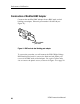
8. Connect the output of the probe to channel 1 of the oscilloscope.
9. Attach the Modified BNC adapter to the SIG OUT of the
generator.