
User's Manual


Performance Verification
P5205 Instructi on Manual
31
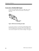
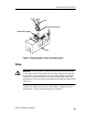
10. Attach the differential probe input l eads (without attachment
accessories) by sliding the banana plug of the leads onto the
binding posts m etal sleeves on the Modified BNC adapter
(see Figure 13).
(+) Post
(--) Post
Modified BNC adapter
Banana plug of probe
input lead
Figure 13: Slide probe leads onto the binding posts
WARNING. To reduce the risk of electric shock, ensure the gene rator
output is disabled before modifying/disconnecting test setup or
connect ions since exposed met al may at a hazardous potential. It is
recommended t hat t he generator output amplitude be reduced to
minimum prior to disabling t he output.
11. Set the probe to 500X (out). Set the generator for a 100 V and
1 kHz standard amplitude output (AUX, square wave, 1 MΩ
load).
12. Reduce the amplitude on the generator to minimum then enable
the output.
13. Adjust the zero offset on the compensation box of the probe for
zero offset.
14. Record the DC amplitude of t he square wave (∼100 V) and divide
1/1000
th
of this into the amplitude of just the oscilloscope (refer
to step 6). Verify that only the probe gain accuracy
is ᐔ3%.