
User's Manual


Performance Verification
P5205 Instructi on Manual
33
7. Set the generator to 100 MHz, and set the oscilloscope to
5 ns/division. Check for ≥ 2.1 V amplitude.
8. Disconnect the setup.
DC CMRR
1. Set the attenuation of the probe to 50X.
2. Set the oscilloscope input coupling to DC, the vertical to
50 mV/div, a nd the seconds/div to 200 s. Center the trace on t he
display. Set the acquisition mode to average 32.
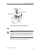
3. Attach the BNC-female-to-dual-banana adapte r to the DC output
of the generator (front of Wavetek 9100). Attach the modified
BNC adapt er to the BNC-female-to-dual-banana adapter.
4. Attach the plunger clamps on t he differential probe input leads.
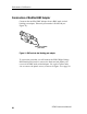
5. Twist the input l eads together as shown in Figure 3 on page 13,
and connect both probe inputs to the positive terminal of the
modified BNC adapter.
6. Adjust the offset on the probe output to zero.
WARNING. Generator produces hazardous voltages. To avoid risk of
shock, do not touch exposed metal parts after t he generator output is
enabled.
7. Set the output of the generator to 500 VDC.
8. Enable the output.
9. Check that the trace on the oscilloscope shifts less than 3.33
divisions (167 m V) from center.
10. Disable the generator output.